
24VDC-220VDC vehicle carried switching power supply based on inverter circuit
The circuit topology represents a sophisticated power conversion system designed to efficiently manage energy transformation from low-voltage direct current to high-voltage alternating current. The use of a push-pull inverter allows for effective utilization of transformer cores, optimizing performance in applications requiring moderate power levels. The DC-DC converter stage, employing high-frequency components, enhances the overall efficiency of the system while addressing the challenges posed by inductive elements within the circuit. The design considerations, including the duty cycle management and peak voltage suppression, contribute significantly to the reliability and efficiency of the power conversion process. The integration of feedback mechanisms through the flywheel diode further ensures that energy losses are minimized, promoting a more sustainable operation of the power supply system. Overall, this circuit serves as a critical component in modern vehicle electrical systems, supporting the diverse power needs of contemporary electrical devices.With the increase of the modern electrical equipment kind for vehicle, the increase of the power level, there are more and more patterns of power needed, including AC supply and direct current power supply. The power needs to adopt the switch converter the direct-current volts of 12VDC or 24VDC that the storage battery will be offered will be prom
oted as 220VDC or 240VDC through DC-DC converter, the final-stage is changed into the AC supply or frequency conversion voltage adjustable power source of mains frequency through DC-AC converter again. As to the preceding stage DC-DC converter, include again high-frequency DC-AC reverses some, high-frequency voltage transformer and AC-DC and commutates the part, different associations meet different power levels of output, it is different to vary the characteristic to some extent too.
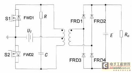
The inverter circuit of push pull is simple in construction with it, the higher advantage of utilization factor of magnetic core of voltage transformer is used widely, especially the middle low power occasion in great current input of undervoltage; Full bridge rectifier have the intersection of voltage and high supporting the intersection of output power and great characteristic utilization factor too at the same time, so a literary grace is reversed with the push pull the high-frequency voltage transformer full-bridge commutates the scheme, design 24VDC input the intersection of 220VDC and output, specified the intersection of output power and the intersection of DC-DC and converter of 600W, and adopt AP law to design the corresponding push pull voltage transformer. Fig. 1 provides the push pull to reverse high-frequency voltage transformation basic circuit topology that the full-bridge commutated DC-DC converter.
Through controlling two gas switching tubes S1 and S2 to turn on the same switching frequency alternatively, and the duty ratio d of each gas switching tube is smaller than 50%, reserves certain Dead Time in order to avoid S1 and S2 shoot-through. Will be reversed and will input the direct-flow low-voltage to go against and turn into and will exchange the high-frequency low-voltage by the push pull of the preceding stage, send to the primary side of the high-frequency voltage transformer, and couple through the voltage transformer, is exchanged the high-frequency upper voltage on the secondary, and then receive the desired direct-flow upper voltage after commutated, filtered by the full-bridge formed of the fast recovery diode FRD backward.
Because it is the input voltage of twice that the back pressure that the gas switching tube can be born is minimum, namely 2UI, but the electric current is the rated current, so, the push-pull circuit is generally used in the middle low power occasion lower in input voltage. When S1 opens, the feed-through pressure drop that the voltage uDS1 of its drain voltage is only a gas switching tube, can assume uDS1 in ideal cases =0, And will have produced by one of induced voltages at this moment because in being at coil, and according to voltage transformer that primary winding end relation, this induced voltage will be superposed on S2 getting and shutting off too, thus make the sum that the voltage that S2 bears during shutoff is input voltage and induced voltage about 2 UI.
in practice, the leakage inductance of the voltage transformer will produce very large Peak voltage to add at S2 both ends, thus cause great shutoff to loss, because the efficiency of the converter is limited by voltage transformer leakage inductance, it is not very high. In RC buffer circuit in the indirectness of the drains of S1 and S2, is called the absorbing circuit, is used for inhibiting the formulation of the Peak voltage.
And in order to offer the feedback loop for that energy is repaid, connect the upper fly-wheel diode FWD in parallel at S1 and S2 both ends instead. Adopt area product AP France designs. Reverse the s 🔗 External reference
Related Circuits
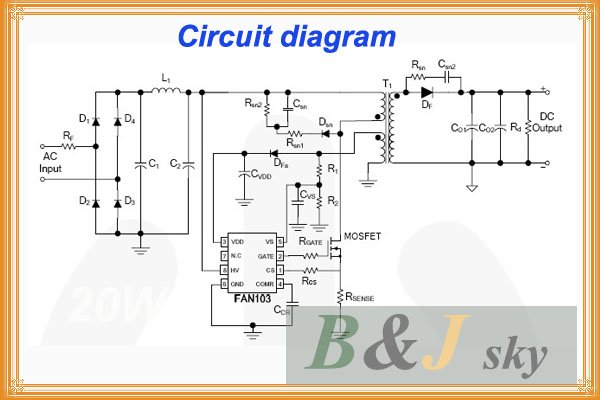
This lighting solution offers over 90% energy savings compared to incandescent or halogen bulbs, with a lifespan exceeding 50,000 hours. It operates without flickering, making it suitable for human eyes, and produces no RF interference or UV radiation. The...
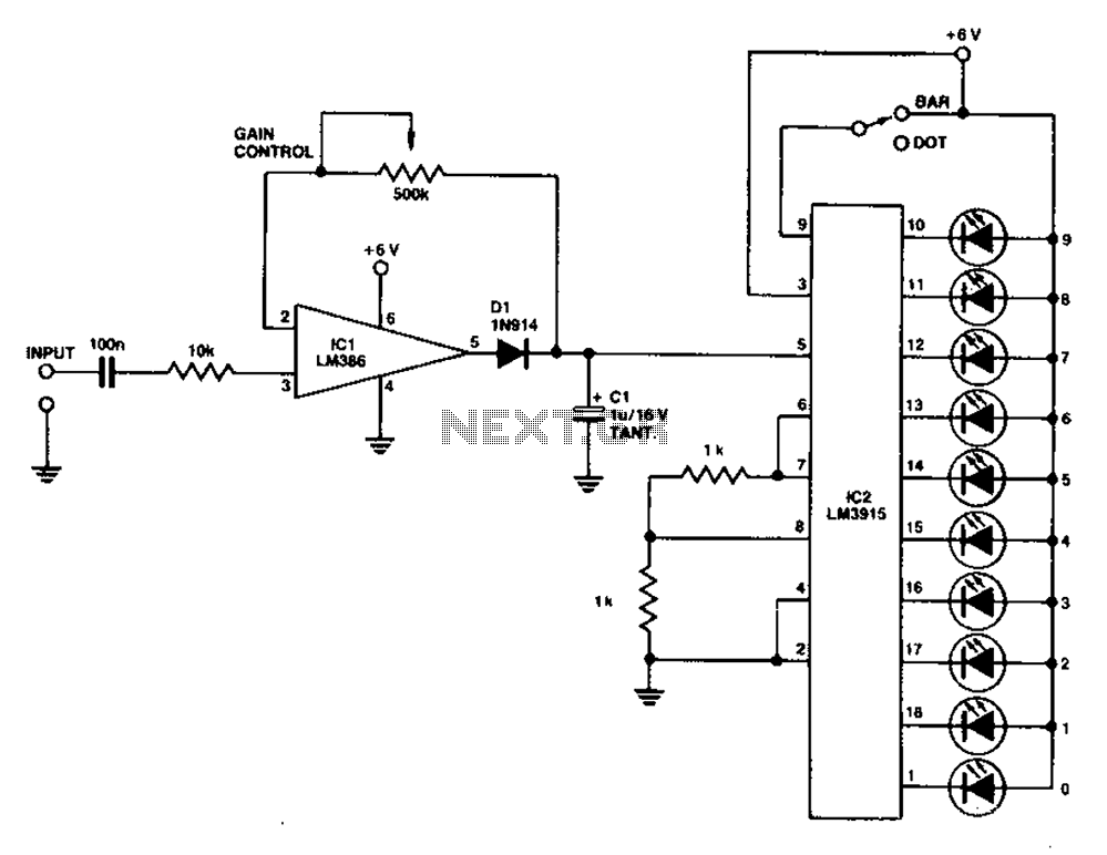
A simple level power meter designed to provide a high-fidelity sound system with a bar or dot matrix display. The green LED display indicates levels from 0 to 7; level 8 is shown in yellow, and level 9 is...
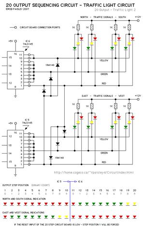
The current application involves the use of the VHDL hardware description language for designing a traffic light system controller circuit. This design is implemented within the Altera MAX PLUS EDA software environment, which facilitates compilation, simulation, and programming for...
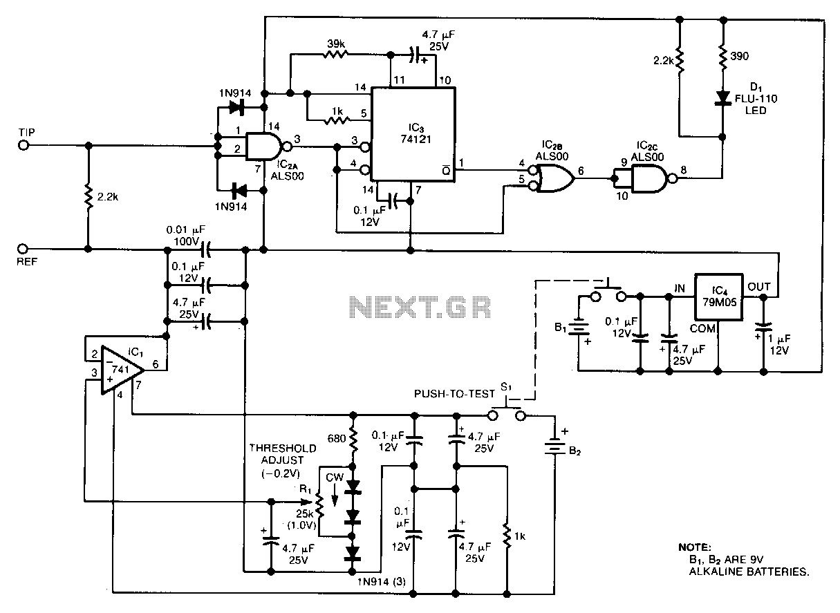
Oscilloscope measurements of ground noise can be unreliable because noise can enter your circuit via the scope's three-pronged power plug. This issue can be mitigated by utilizing the ground-noise tester described. The circuit operates on two 9-V batteries and...
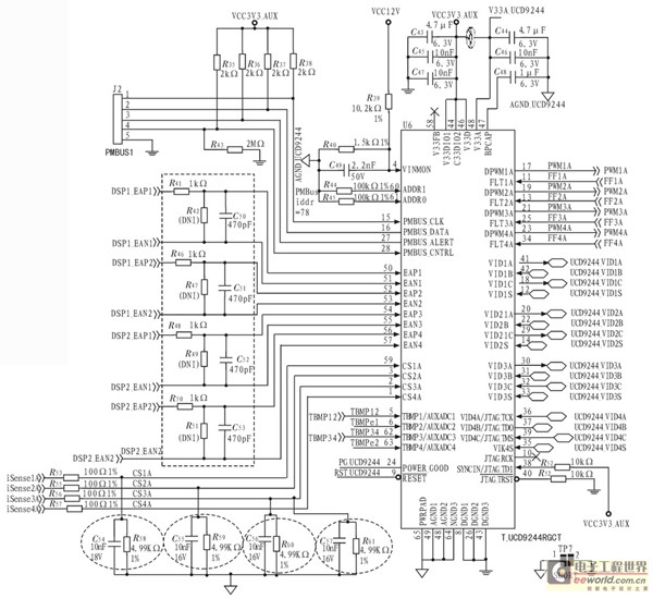
The TMS320C6678 DSP is a component of the DSP based on the KeyStone framework recently released by Texas Instruments. It features 8 cores and achieves operating speeds that can reach up to 10 GHz. However, it has high power...
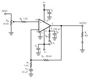
The Audio Power Amplifier is a crucial component in sound reproduction within audio systems. The LM3886 Audio Power Amplifier is a highly capable integrated circuit that can deliver 68 Watts of power with a 4 Ohm load and 38...
Warning: include(partials/cookie-banner.php): Failed to open stream: Permission denied in /var/www/html/nextgr/view-circuit.php on line 713
Warning: include(): Failed opening 'partials/cookie-banner.php' for inclusion (include_path='.:/usr/share/php') in /var/www/html/nextgr/view-circuit.php on line 713