
25kHz using thyristor inverter welding machine circuit
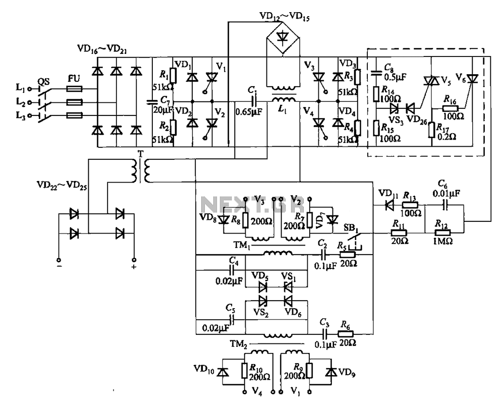
The thyristor inverter welding machine operates at a frequency of 25kHz, which significantly enhances its efficiency and allows for a more compact transformer design compared to traditional welding machines. The power section is responsible for converting the incoming AC supply into a suitable DC voltage using a series of diodes and filter capacitors to smooth the output.
The inverter section plays a crucial role in converting the DC voltage back into high-frequency AC voltage, which is necessary for effective arc welding. This section utilizes silicon-controlled rectifiers (SCRs) and various passive components to manage the switching and control of the output waveform, ensuring a stable and consistent arc during the welding process.
The flip-flop section provides the necessary pulse signals to drive the inverter, utilizing pulse transformers and RC timing circuits to generate the required switching frequencies. This section is vital for maintaining the high-frequency operation of the inverter and ensuring that the welding process remains efficient.
The output unit is designed to deliver the high-frequency AC voltage to the welding electrode. It consists of a transformer that steps up the voltage as needed, along with diodes that rectify any back EMF generated during the welding process, protecting the circuit from potential damage.
Finally, the arc suppression circuitry is critical for preventing unwanted arcing and ensuring a smooth welding operation. It employs a combination of triacs, thyristors, regulators, diodes, capacitors, and resistors to manage the arc characteristics and maintain a stable welding arc.
Overall, this thyristor inverter welding machine circuit exemplifies advanced design techniques that leverage high-frequency operation for improved performance and reduced size, making it suitable for a variety of welding applications.25kHz using thyristor inverter welding machine circuit Using high frequency 25kHz, thyristor inverter arc welding machine, which can be smaller transformer, the circuit shown i n Figure 9-14. The machine no-load output voltage of 45V DC, 90V (peak), the short-circuit current of 125A DC. Circuit consists of five parts: Power section (by the diode VD16 ~ VD2 [filter capacitor C7 etc.), the inverter section points (by the diode VDi ~ VD4, SCR Vl-V4, resistor Ri-R4, capacitors and inductors Li CL, etc. composition), touch -flop (by a pulse transformer TMi, TMz and associated RC components, diodes, regulator etc.), an output unit divided (by the transformer T and the diode VD22 ~ VD25 etc.) and arc suppression circuitry (by the Triac V5, thyristor V5, the regulator VS3, diode VD, 6, capacitor C8, resistor R14 ~ Rl7 etc.).
Related Circuits
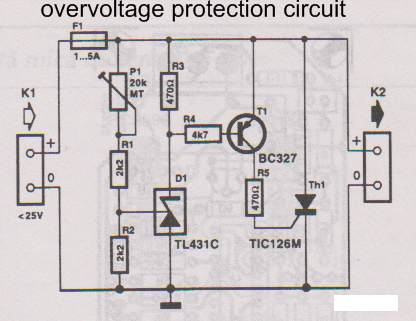
This overvoltage protection or crowbar protection circuit is used where protection against high voltage surges is necessary. The circuit consists of several components. This overvoltage protection circuit, commonly referred to as a crowbar circuit, serves as a critical safety mechanism...
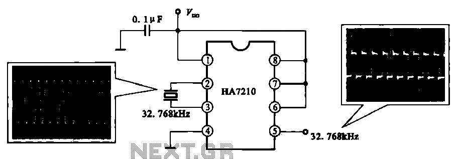
This circuit illustrates a 32.768 kHz micro-power clock oscillator, suitable for use in mobile phones, laptop computers, and home appliances. It generates a clock signal that can be utilized in various applications. The 32.768 kHz micro-power clock oscillator circuit is...

This sound-activated switch allows for control through sound, which can be beneficial not only in robotics but also in home automation applications. The sound-activated switch operates by detecting specific sound frequencies or patterns, typically using a microphone or a sound...
Average vending machines are commonly found at railway stations, airports, fast-food restaurants, and even within companies. When a switch is pressed, the machine dispenses a cup of the selected beverage. Although this process appears straightforward, it involves complex logic,...
This circuit is designed to indicate when a plant requires watering. An LED blinks at a low frequency when the soil in the flower pot is excessively dry, turning off as the moisture level rises. The sensitivity of the...
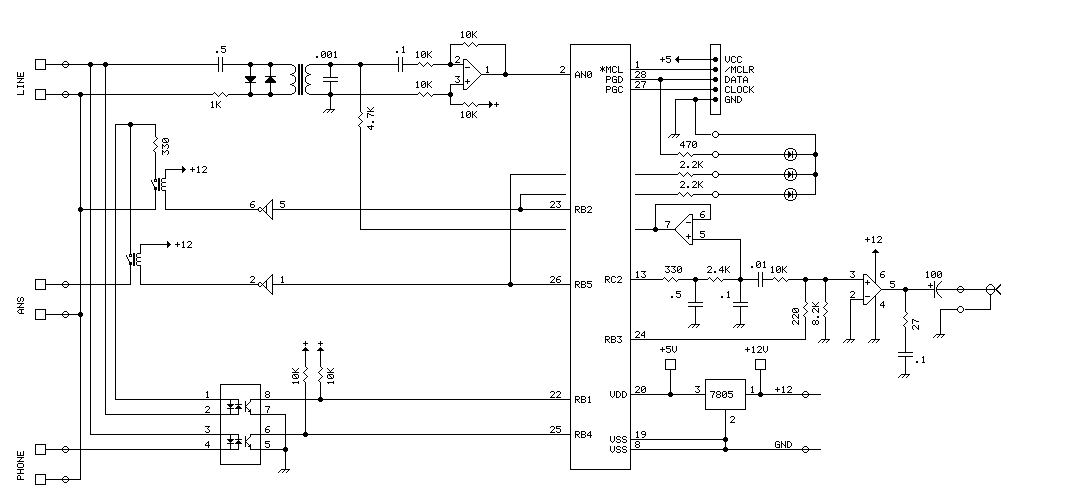
The PIC16F870 chosen for this project has several analog channels. One of these is used to capture the DTMF tones and decode the digits. The actual phone connections are made using a 'hacked' 5 line expander from Radio Shack....
Warning: include(partials/cookie-banner.php): Failed to open stream: Permission denied in /var/www/html/nextgr/view-circuit.php on line 713
Warning: include(): Failed opening 'partials/cookie-banner.php' for inclusion (include_path='.:/usr/share/php') in /var/www/html/nextgr/view-circuit.php on line 713