
Plant Watering Watcher Circuit Schematic
The circuit utilizes a moisture sensor that detects the water content in the soil. When the soil moisture drops below a predetermined threshold, the sensor triggers a comparator circuit. This comparator is typically configured with a reference voltage that corresponds to the desired moisture level. The output of the comparator is connected to a microcontroller or a simple transistor switch that controls the LED.
In this setup, the LED serves as a visual indicator of the soil's moisture condition. The blinking rate of the LED can be influenced by the design of the timing circuit, which may include components like capacitors and additional resistors. The adjustment of R2 allows for fine-tuning of the sensitivity, ensuring that the circuit can effectively respond to different environmental conditions and soil compositions.
For optimal performance, the moisture sensor should be positioned at an appropriate depth within the soil, ensuring accurate readings. The circuit may also benefit from additional features such as a power-saving mode to prolong battery life or the incorporation of a buzzer for audible alerts. Overall, this moisture-sensing circuit is a practical solution for plant care, providing timely notifications to users regarding the watering needs of their plants.This circuit is intended to signal when a plant needs water. A LED flashes at a low rate when the ground in the flower-pot is too dry, turning off when the moisture level is increasing. Adjusting R2 will allow the user to adapt the sensitivity of the circuit for different grounds, pots and probe types
🔗 External reference
Related Circuits
The lamps are usually used as ballast or electronic ballast inverter. Here it is used to reduce voltage capacitor reactance. Interesting is also the method of ignition of the auxiliary electrodes involved over 150 Ohm resistors. To start simply...
This AC to DC power supply can output 5A in continuous operation and 12A peak current. This type of DC power supply uses a PCB, allowing for two case types. The described AC to DC power supply is designed to...
This integrated circuit (IC) requires fewer external components, making it simpler for beginners to assemble it on a veroboard. The original circuit was sourced from its datasheet. A slightly modified version of the circuit is presented below. This circuit...

The rectifier input is connected to the input, establishing a relationship where gain is inversely proportional to the input level. Consequently, a 20-dB reduction in input level results in a 20-dB increase in gain. The output is designed to...

This is a Lithium-ion charger for LiPo batteries. The circuit schematic illustrates the configuration for charging a single 3.7V LiPo battery, but the voltage can be adjusted to charge multiple batteries in series. The LiPo charger establishes a current...
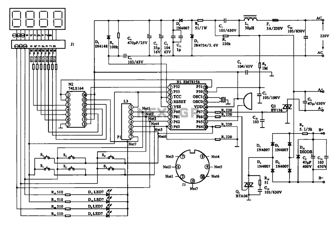
The display circuit is utilized in a typical digital massager. At the heart of the control circuit is the microprocessor EM78156, which receives manual operation instructions. It triggers two transistors to supply voltage to the DC motor (A +,...
Warning: include(partials/cookie-banner.php): Failed to open stream: Permission denied in /var/www/html/nextgr/view-circuit.php on line 713
Warning: include(): Failed opening 'partials/cookie-banner.php' for inclusion (include_path='.:/usr/share/php') in /var/www/html/nextgr/view-circuit.php on line 713