
25W HiFi Audio Amplifier with MOSFET

This circuit design is versatile and can be effectively utilized in various audio applications. The integration of a dual-gang potentiometer allows for precise volume control in stereo setups, enhancing user experience. The grounding strategy is critical; by connecting the grounds of multiple components at a single point, the design minimizes potential noise issues that can arise from ground loops. This is particularly important in audio circuits where hum can significantly degrade sound quality.
The amplifier section, utilizing the LM1875, is capable of delivering substantial power while maintaining fidelity, making it suitable for high-quality audio reproduction. The choice of resistors and capacitors in the design ensures that the amplifier operates within optimal parameters, providing clear and powerful sound output.
In addition, the inclusion of switchable sensitivity inputs allows the mixer circuit to accommodate various audio sources, enhancing its functionality in different scenarios. The use of linear potentiometers for input adjustment provides smooth control over the audio levels.
The dancing LED circuit serves as an engaging visual representation of audio levels, making it a popular addition to audio equipment. The design of this circuit ensures that the LEDs respond dynamically to sound, providing an interactive element that can enhance the overall aesthetic of an audio setup.
Overall, the combination of these circuits creates a comprehensive audio system that is both functional and visually appealing, suitable for a range of applications from home audio systems to live performances.Can be directly connected to CD players, tuners and tape recorders. Simply add a 10K Log potentiometer (dual gang for stereo) and a switch to cope with the various sources you need. A correct grounding is very important to eliminate hum and ground loops. Connect in the same point the ground sides of R1, R4, R9, C3 to C8. Connect C11 at output grou nd. Then connect separately the input and output grounds at power supply ground. This circuit diagram is quite simple and cheap. Amplifier parts: P1 = 22K Log. Potentiometer (Dual-gang for stereo) R1 = 1K 1/4W Resistor R2 = 4K7 1/4W Resistor R3 = 100R 1/4W Resistor R4 = 4K7 1/4W Resistor R5 = 82K 1/4W Resistor R6 = 10R 1/2W Resistor R7 = R22 4W Resistor (wirewound) R8 =. Simple and cheap mixer circuit. This circuit supplied using 9V power supply. There is high/low-sensitivity switchable inputs for each input channel. Component part list: P1, P2, P3_5K Linear Potentiometers R1, R11, R15_180K 1/4W Resistors R2, R12, R16_2M2 1/4W Resistors R3, R13, R17_750R 1/4W Resistors (See Notes) R4, R14, R18_1K 1/4W Resistors R5_15K 1/4W Resistor R6_220R 1/4W Resistor R7_1K5 1/4W Resistor R8_820R 1/4W Resistor R9_150R 1/4W.
Here the circuit diagram of 25 watt high fidelity audio amplifier that build based on single Power Amplifier IC LM1875. Component part list R1 _ 1K R2 _ 1M R3 _ 22K R4 _ 10K R5 _ 180K R6 _ 1R IC1 _ LM1875 C1 _ 1uF 50V C2, 6 _ 100nF C3 _ 22uF 63V.
Build based operational amplifier NE5532 and a couple of power transistor TIP41A / TIP42A, this audio amplifier circuit has capability to deliver up to 10W audio power output into 8 ohm speaker. Amplifier Parts list: P1 22K = Log. Potentiometer P2 = 100K Log. Potentiometer R1 = 820R R2, R4, R8 = 4K7 R3 = 500R Trimpot. This is the circuit of dancing LEDs which consists of 10 units LEDs. The circuit works like a audio level meter. The LEDs will be dance sequence with the sound level that entering the microphone. Components list: R1_10K 1/4W Resistor R2, R3_47K 1/4W Resistors R4_1K 1/4W Resistor R5, R6, R7_100K 1/4W Resistors R8_820R 1/4W Resistor C1, C3_100nF 63V Ceramic.
🔗 External reference
Related Circuits
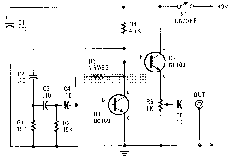
This circuit generates a sinusoidal output of approximately 8 V peak-to-peak, which can be adjusted down to zero, operating at a frequency of about 500 Hz. The signal is produced by a phase-shift oscillator. The described circuit utilizes a phase-shift...
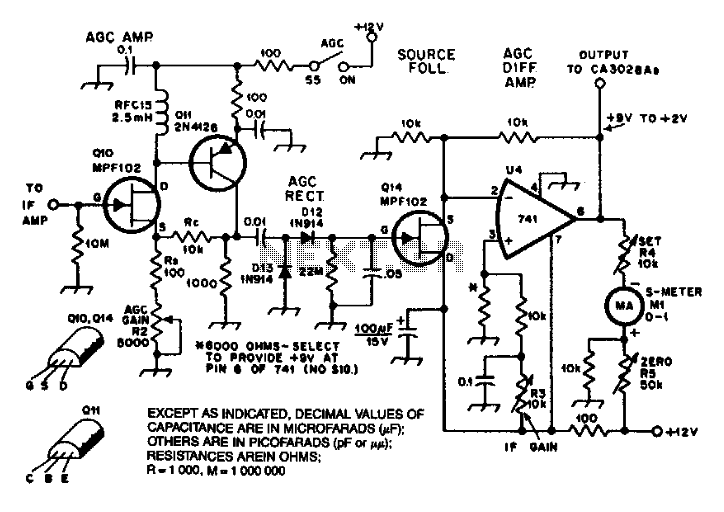
An MPF102 amplifier supplies intermediate frequency (IF) signals to a 2N4126 transistor. A potentiometer in the source of the MPF102 functions as a gain control. The voltage from this configuration is rectified by an 1N914 doubling detector and subsequently...
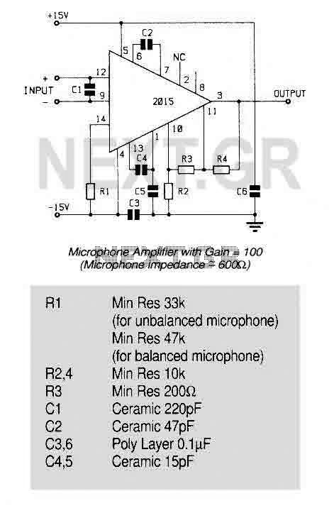
An ultra low noise audio preamplifier particularly suited to microphone preamplification including balanced microphones. The IC features wide bandwidth, low distortion only 0.007% at a gain of 100, and very low noise only 1.3nV/Hz for source impedance up to...
A general purpose audio power amplifier is a must have for the electronics amateur. It's not a good thing to use your HiFi set for an experiment, when there's a risk of blowing its transistor out. Amplifier for your...
A request for a DIY 300BSE power amplifier schematic is made, with a specification to utilize Lowther PM6 speakers. The 300BSE power amplifier is a well-regarded audio amplification circuit known for its warm sound and high fidelity, particularly suited for...
The 60 Watt linear amplifier is a simple all solid state circuit using power mosfet IRF840. The IRF series of power transistors are available in various voltage and power ratings. A single IRF840 can handle a maximum power output...