
300BSE power amplifier circuit

The 300BSE power amplifier is a well-regarded audio amplification circuit known for its warm sound and high fidelity, particularly suited for driving high-efficiency speakers like the Lowther PM6. The 300B vacuum tube, which operates in a single-ended configuration, provides a unique tonal quality and is favored in high-end audio applications.
The schematic for a 300BSE amplifier typically includes the following components:
1. **Power Supply**: A robust power supply circuit is essential for the 300BSE amplifier. It generally consists of a high-voltage transformer, rectifier diodes, and filter capacitors to provide stable DC voltage to the 300B tubes. The power supply should be designed to deliver around 300V to 400V for optimal tube operation.
2. **Input Stage**: The input stage usually employs a low-noise tube (such as a 6SN7 or 12AX7) to amplify the audio signal before it reaches the output stage. This stage may include a coupling capacitor to block DC and allow only the AC audio signal to pass.
3. **Driver Stage**: The driver stage is crucial for driving the 300B output tubes. A common configuration uses another gain stage, often with a 6SL7 or similar tube, which provides the necessary voltage gain and drives the output stage efficiently.
4. **Output Stage**: The output stage consists of the 300B tubes connected in a single-ended configuration. Each 300B tube typically has a cathode resistor for biasing, and a transformer is used to match the output impedance to the speaker load. The output transformer should be selected based on the impedance of the Lowther PM6 speakers, which are typically rated at around 8 ohms.
5. **Feedback Loop**: Some designs incorporate a feedback loop to improve linearity and reduce distortion. This can be done by taking a portion of the output signal and feeding it back to the input stage.
6. **Output Terminals**: The amplifier will have output terminals for connecting to the Lowther PM6 speakers, ensuring that the connections are secure and capable of handling the power output without introducing noise.
7. **Chassis and Layout**: The physical layout of the components should be carefully planned to minimize noise and interference. The use of a metal chassis can help shield the circuit from electromagnetic interference.
Overall, the 300BSE amplifier design is characterized by its simplicity and elegance, allowing for a high-quality audio experience when paired with efficient speakers like the Lowther PM6. Proper attention to component selection and circuit layout will ensure a robust and reliable amplifier.Hi! I want to DIY a 300BSE power amplifier recently, could somebody recomend or provide me a wonderful and robust schematic??? I will use Lowther PM6.. 🔗 External reference
Related Circuits
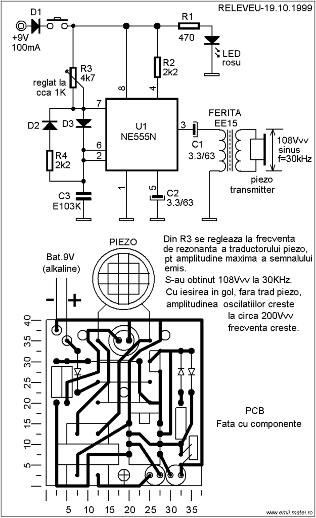
This ultrasonic dog repeller circuit is designed to deter aggressive dogs. It is constructed using the well-known 555 timer circuit, a buzzer, and a small ferrite transformer. The ultrasonic dog repeller circuit operates by emitting high-frequency sound waves that are...
This chapter presents a variety of circuits for basic power supplies, including both line-powered and inverter types, some of which feature regulators, modulation inputs, and additional functionalities. Several circuits have been reverse-engineered from actual commercial products, and others, designed...
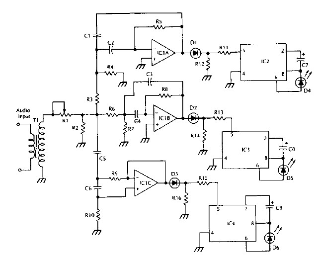
The LM 3909 LED flasher integrated circuit (IC) can be utilized to design various electronic projects. A circuit diagram illustrates the creation of a simple color organ using the LM3909 LED flasher IC. Three active filters process the audio...
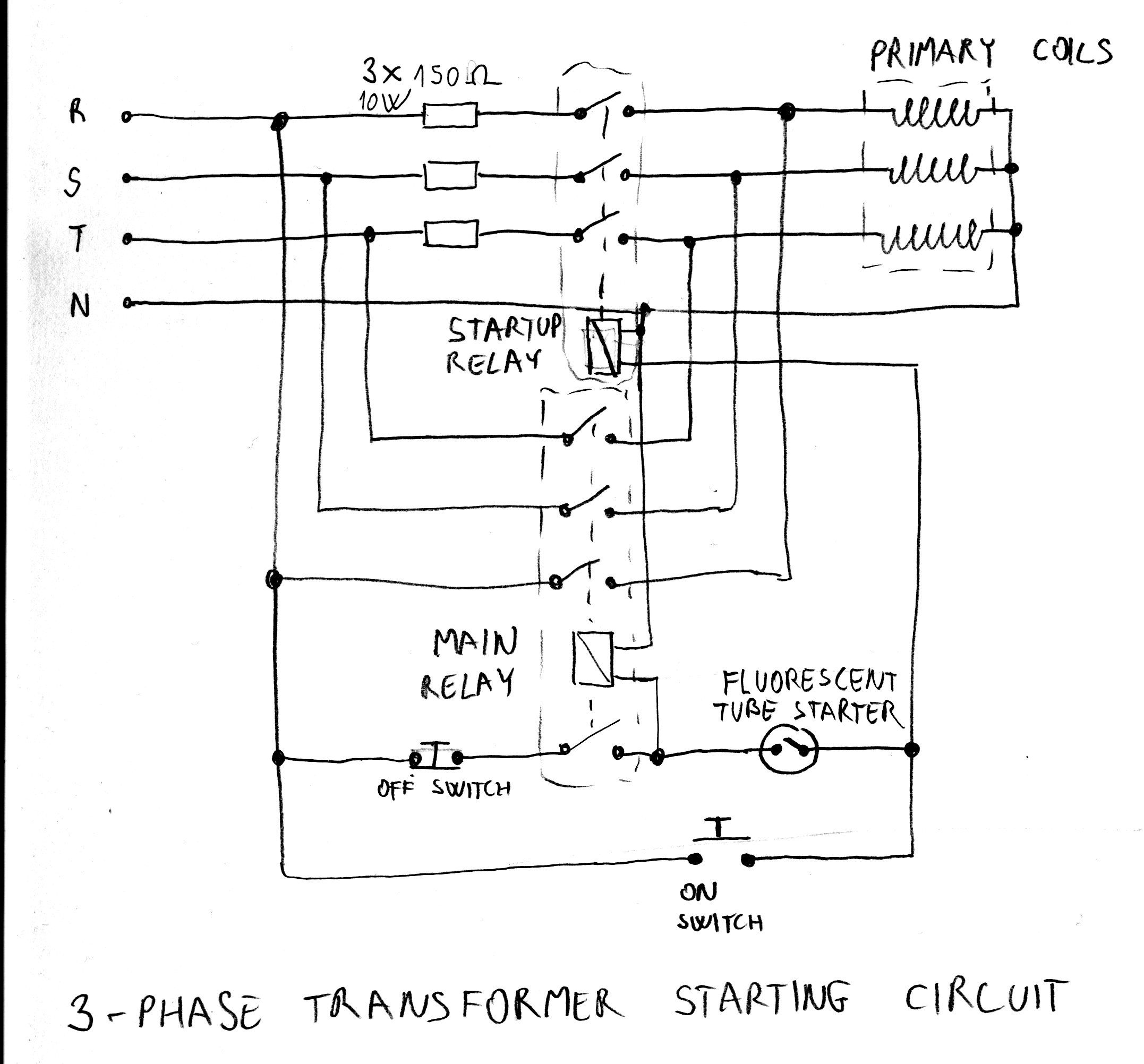
After acquiring a large 3-phase variable transformer (variac), there was an unexpected issue with it tripping circuit breakers at random when plugged in. Interestingly, the tripping occurred on different phases and seldom affected all three simultaneously. Resetting the breakers...
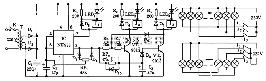
The controller features a buck rectifier circuit utilizing a 555 multivibrator, designed for controlling approximately 220V, 5W low-power parallel lights or 6 to 12V small bulb series. The 555 timer, along with components D3, D4, RP1, and C2, forms...
This circuit performs a rapid battery test without requiring a power supply or costly moving-coil voltmeters. It offers two testing ranges: when switch SW1 is positioned as indicated in the circuit diagram, the device can test batteries ranging from...