
60 WATTS LINEAR AMPLIFIER

The 60 Watt linear amplifier circuit utilizes the IRF840 power MOSFET, which is well-suited for high-power applications due to its high efficiency and thermal stability. The IRF840 is a N-channel MOSFET with a maximum drain-source voltage of 500V and a continuous drain current rating of 8A, making it capable of handling substantial power levels without overheating, provided that adequate thermal management is implemented.
In the design of the amplifier, the input stage is typically configured to accept low-level audio signals, which are then amplified by the IRF840. The MOSFET operates in the linear region, allowing for high-fidelity amplification of the input signal. The gain of the circuit can be adjusted by varying the gate resistors, providing flexibility in tuning the amplifier's performance.
The circuit is powered by a 60V power supply, which is essential for achieving the desired output power. The current draw of 700 mA indicates that the amplifier is designed to operate efficiently within this voltage range, delivering the specified 60 Watts of output power. It is important to ensure that the power supply can provide sufficient current without significant voltage drop, which could affect performance.
Thermal management is critical in this application, as the IRF840 will dissipate heat during operation. A heat sink is required to maintain the junction temperature within safe limits, preventing thermal runaway and ensuring reliable operation. The selection of a heat sink should be based on the thermal resistance required to keep the MOSFET within its specified temperature range under full load conditions.
The output of the amplifier can be connected to various loads, including speakers or antennas, depending on the intended application. It is advisable to incorporate output protection circuitry to prevent damage from short circuits or excessive load conditions.
Overall, the 60 Watt linear amplifier using the IRF840 is a robust design suitable for various audio and RF applications, combining simplicity with effective performance. Proper implementation of the circuit layout, component selection, and thermal management will ensure optimal functionality and longevity of the amplifier.The 60 Watt linear amplifier is simple all solid state circuit using power mosfet IRF840. The IRF series of power transistors are available in various voltage and power ratings. A single IRF840 can handle maximum power output of 125 watts. Since these transistors are used in inverters and smps they are easily available for around Rs: 20/-. The IRF linear amplifier can be connected to the out put of popular VWN-QRP to get an output of 60 Watts.
The circuit draws 700 ma at 60 Volt Vcc. Good heat sink is a must for the power transistor. 🔗 External reference
Related Circuits
High-quality amplifier for headphones electronics project. No need for preamplifier. Circuit diagram. The described project involves the design of a high-quality headphone amplifier that operates without the necessity of a preamplifier stage. This simplifies the circuit while still delivering superior...
The Electronics Schematic Diagram MJR7-Mk3 Mosfet MJR6 page includes distortion extracted using the nulling method with a speaker load and a music signal to demonstrate that these designs have no audible distortion in normal use. The MJR7 has even...
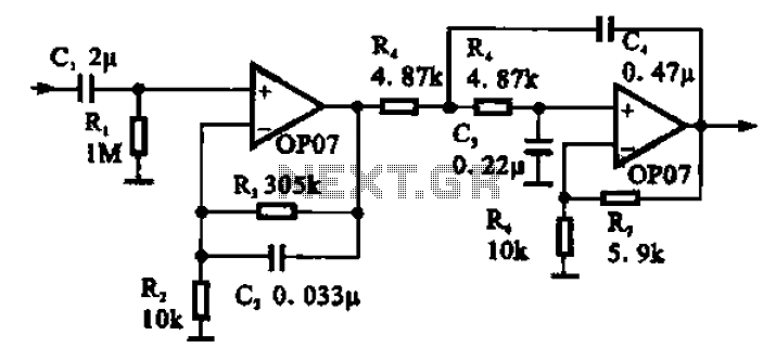
Broadband 0.1 to 10 Hz filter amplifier. The broadband circuit consists of two operational amplifiers configured as filter amplifiers operating in the frequency range of 0.1 to 10 Hz. The broadband filter amplifier circuit utilizes two operational amplifiers (op-amps) to...
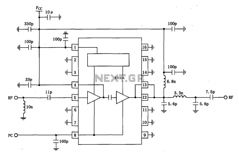
The RF2104 830MHz amplifier circuit operates as illustrated in the figure. A radio frequency (RF) signal enters through a 5-foot input, passes through a preamplifier, and is then amplified by an amplifier stage at the 12-pin output. The circuit...
This simple audio power amplifier was originally designed for a circuit board workshop conducted by the OSU IEEE Student Group. At the workshop, 20 participants each constructed this amplifier by etching and drilling the single-sided circuit board, soldering all...
The achievement of this 30 watt amp was thought to take place on a heatsink microprocessor PC. Equipped with its fans, the advantage of this method of cooling was chosen for the fact it is common and not very...