
Distortion In Power Amplifiers
Audio engineering is often plagued by misinformation and misunderstandings. Three distortions are frequently cited as serious degradation sources but either do not exist in detectable quantities or are based on misconceptions. The only likely manifestations are Distortion 5 and 6, as described below. If these two mechanisms are effectively suppressed (which is straightforward) and the amplifier possesses sufficient power-supply rejection to keep hum and ripple below the noise floor, there should be no other means by which the power supply can degrade linearity. This phenomenon does not appear to exist at detectable levels in standard amplifier circuitry. However, it is true that if an amplifier operates under certain conditions, it may exhibit specific performance issues.
The understanding of distortion mechanisms in solid-state Class-B amplifiers is crucial for designing high-fidelity audio systems. By isolating and addressing the individual distortion sources, engineers can create amplifiers that not only meet but exceed current performance benchmarks, ensuring a superior audio experience for users. The exploration of these mechanisms and their implications on amplifier design remains a vital area of research in audio engineering.The distortion produced by a typical solid-state Class-B power amplifier is shown to consist of eight mechanisms, all of which may co- exist and whose distortion products overlap to give a complex result. Methods for isolating each mechanism for study, and minimising its contribution, are given. If the avoidable distortions are designed out, Class -B amplifiers of unusually low distortion (Below 0. 0005% at 1kHz, 0. 003% at 10 kHz) may be designed as a matter of routine, and without significant extra cost. Such amplifiers define a distortion benchmark, and I have named them "Blameless" amplifiers. Considering the economic importance of audio power amplifiers, surprisingly little reliable information has been published on their design. Distortion in particular has been neglected, although it is the most variable feature of amplifier performance.
You may have two units placed side, one giving 2% THD and the other 0. 0005% at full power, and both claiming to provide the ultimate audio experience. I investigated the origins of distortion in the period 1992-94, and determined that power amplifier distortion, traditionally a difficult and mysterious thing to grapple with, was the amalgamation of eight basic mechanisms, superimposed and sometimes partially cancelling, giving a complex result. I evolved ways of measuring and minimising each distortion mechanism separately, and the result is a design methodology for making Class-B or Class-A amplifiers with distortion performance so good that two or three years ago it would have been regarded as impossible.
0. 0008% at 1 kHz and 0. 003% at 10 kHz are easily obtained. The methodology gives reliable and repeatable results with moderate amounts of negative feedback; increases in complexity and cost are insignificant. Fig 1a shows the generic Lin power amplifier circuit, with the now universal differential input stage, representing something like 98% of the amplifiers ever built.
It is the obvious starting point for amplifier investigation. [1] Fig 3 shows its distortion plot; there are two distortion regimes. Below 1 kHz THD is low at 0. 002% but not zero, the noise floor being 0. 0006% approx. Above 1 kHz, THD quadruples with each octave and reaches 0. 5% before 20 kHz. The basic topology is a transconductance amplifier (voltage- difference input, current output) driving a transimpedance (current-to- voltage converter) Voltage Amplifier Stage, followed by a unity-gain power buffer. The voltage at the VAS transistor base is typically only a couple of millivolts, and is of little interest in itself; it is the current passed from the input stage to the VAS that counts.
This topology has many advantages, including simple compensation. [2] The distortion mechanisms of a generic power amplifier fall into eight basic categories. Distortion 3 is that generated by the output stage, subdivided into three different mechanisms 3a, 3b, 3c that are unrelated in their physical origin. Similarly, Distortion 8 normally only occurs in the capacitor at the bottom the feedback arm; however, in AC-coupled designs the output capacitor may contribute significant distortion.
3. THREE NON-EXISTENT DISTORTIONS. Audio engineering suffers from misinformation, disinformation, and downright lying more than most fields of endeavour. Here are three distortions which either do not exist in detectable quantities or are based on misunderstandings: This is often cited as a serious source of degradation.
The only likely manifestations are Distortion 5 and 6, described below. Providing these two mechanisms have been suppressed (which is straightforward) and the amplifier has sufficient power-supply rejection to keep hum and ripple below the noise floor, then there should be no other way in which the power supply can degrade linearity. This does not appear to exist at detectable levels in normal amplifier circuitry. It is however true that if an amplifier is opera 🔗 External reference
Related Circuits
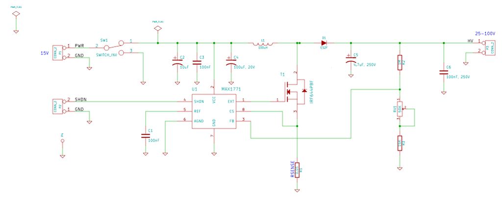
A typical circuit for welding equipment is illustrated in the following circuit diagram. The turn-on delay can be accurately controlled with Potentiometer P2, allowing for effective discharge management. The welding equipment circuit typically incorporates several key components to ensure proper...
The Cymbal monoblock power amplifier features a modern push-pull design utilizing ultra-linear 6H30 triodes in a zero-feedback circuit. This unique configuration is optimized for sound quality rather than sheer power, making it ideal for efficient drivers and horn speakers....
This shows the overall circuit diagram of the power control unit. On the left, there is a main relay controlled by the key switch. The power control unit circuit diagram illustrates the primary components and their interconnections for managing electrical...
In previous Instructables tutorials, equipment used for DNA electrophoresis and imaging has been described. This includes a mini-gel electrophoresis apparatus. The mini-gel electrophoresis apparatus is designed for the separation of nucleic acids such as DNA and RNA. The core components...
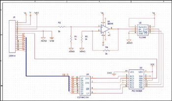
This example demonstrates the design of a circuit that incorporates both analog and digital components, features multiple power planes, and utilizes a single ground plane that is divided into analog and digital sections while maintaining a common reference point. The...
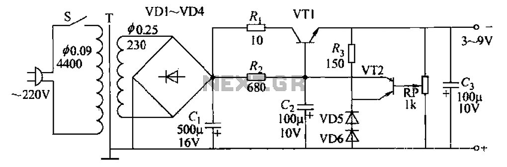
A 3-9V adjustable 100mA power supply is presented, featuring a series regulator circuit that utilizes amplifier tubes. The output voltage can be continuously adjusted between 3V and 9V, with a maximum output current of 100mA, making it suitable for...
Warning: include(partials/cookie-banner.php): Failed to open stream: Permission denied in /var/www/html/nextgr/view-circuit.php on line 713
Warning: include(): Failed opening 'partials/cookie-banner.php' for inclusion (include_path='.:/usr/share/php') in /var/www/html/nextgr/view-circuit.php on line 713