
280 Watt MOSFET Power Amplifier

The amplifier circuit is designed with flexibility in mind, allowing operation across a broad range of supply voltages from ±5V to ±70V. The primary output stage employs lateral MOSFETs, specifically the Hitachi 2SK1058 and 2SJ162, which are optimized for audio applications due to their superior linearity compared to traditional switching MOSFETs. This design choice minimizes distortion and ensures high fidelity audio reproduction.
The amplifier can be configured for either high or low power output, with the low power variant utilizing a single pair of MOSFETs and requiring a maximum supply voltage of ±56V. This configuration is capable of delivering approximately 100W continuous output into 8 ohms and 150W into 4 ohms, with reduced thermal stress on the components. The high power version, which employs dual pairs of MOSFETs, can handle up to ±70V, providing up to 180W RMS into 8 ohms and 250W into 4 ohms.
The output impedance is measured at approximately 10 milliohms, yielding a damping factor of around 800 when driving an 8-ohm load at 1kHz. This high damping factor contributes to better control of the connected speakers, although practical speaker leads will diminish this advantage.
Noise performance is commendable, with a signal-to-noise ratio of 86dB unweighted, indicating that the amplifier remains silent under typical operating conditions. The design also incorporates source resistors for current sharing when multiple MOSFETs are employed, ensuring balanced operation and enhanced thermal performance.
Overall, this amplifier design prioritizes audio quality, reliability, and operational flexibility, making it suitable for a range of audio applications while ensuring ease of construction for hobbyists and professionals alike.This amplifier is designed to be as flexible as possible, with no bad habits. Indeed, it will operate stably with supply voltages as low as +/-5V (completely pointless, but interesting), all the way to the maximum supply voltage of +/-70V. The only change that is needed is to trim the MOSFET bias pot! With the full supply voltage of +/-70V (which must not be exceeded!), RMS power is around 180W into 8 ohms, or 250W into 4ohms.
Short term (or "music") power is typically about 240W into 8 ohms and 380W into 4 ohms. Note that depends to a very great degree on the power supply, and a very robust supply is an absolute requirement for the maximum output. In general, unless you really need the maximum possible power, I suggest that you limit the supply voltage to ±56V using a 40+40V transformer. You will get around 150W into 8 ohms from this supply voltage (short-term), but you also relax the demands placed on the MOSFETs and heatsinks.
Since this amp probably has more power than you will normally ever need, even if you do skimp a little on the transformer, the loss will be very small. In particular, the distortion figures show that amp loading causes only very small variations, with any harmonics being predominantly from my audio oscillator.
There are no visible or audible high order components to the distortion waveform. Output impedance was measured on a fully built amplifier, including the internal wiring. This entails around 200mm of wire in all (per channel), so the output impedance of the amplifier itself is obviously lower than quoted. For an 8 ohm load, the damping factor at 1kHz is around 800 (8 / 10 milliohms) - completely pointless of course, since any speaker lead will ruin that very quickly.
Noise was measured with inputs open-circuited, and at -54dBV may not look too wonderful, however this figure is very pessimistic. Remember that this is the unweighted measurement, with bandwidth extending to well in excess of 100kHz.
Even so, signal to noise ratio (referred to full power) is 86dB unweighted, and the amp is completely silent into typical speakers. Indeed, even connecting a pair of headphones directly to the amp outputs revealed that no noise was audible.
Naturally, your methods of construction will differ from mine, and you may not be able to get the same performance. As shown in the schematics below (figures 1 and 2), the amplifier can be made in high or low power version, and although there is a bit of vacant PCB real estate in the low power design, it is significantly cheaper to make and will be more than sufficient for most constructors.
If this version is built (using only 1 pair of MOSFETs), it is essential to limit the supply voltage to +/-56V so that it can drive both 4 and 8 ohm loads without excess dissipation. With this voltage, expect about 100W continuous into 8 ohms, and around 150W into 4 ohms. Naturally, dual MOSFET pairs may be used at this voltage as well, providing much better thermal performance (and therefore cooler operation), far greater peak current capability and slightly higher power.
This version may be used at any voltage from +/-25V to +/-42V. The MOSFETs used are Hitachi lateral devices, 2SK1058 (N-Channel) and 2SJ162 (P-Channel). These are designed specifically for audio, and are far more linear than the (currently) more common switching devices that many MOSFET amps use. Unfortunately, they are not especially cheap, but their performance in an audio circuit is so much better than vertical MOSFETs, HEXFETs, etc., that there is no comparison.
Note that using HEXFETs or any other vertical MOSFET type is not an option. They will fail in this circuit, as it was not designed to use them. An alternative (and possibly marginally better than the 2SK/2SJ series) is the Exicon ECX10N20 and ECX10P20 (available from Profusion PLC in the UK). These have been used in most of the amps I have built, and they work very well. So potential constructors can verify that the semiconductors are available before purchasing a PCB, this information has now been included.
All other parts are quite standard. The same PCB is used, but has an extra pair of MOSFETs. Since the devices are running in parallel, source resistors are used to force current sharing. Although these may be replaced by wire links, I do not recommend this. This version may be operated at a maximum supply voltage of +/-70V, and will give up to 180W RMS into 8 ohms, and 250W into 4 ohms. Short term (peak) power is around 240W into 8 ohms and 380W into 4 ohms. These figures are very much dependent on your power supply regulation, determined by the VA rating of the transformer, size of filter caps, etc.
Intermodulation distortion cannot be measured with the equipment I have available, but I have included a screen capture of the three measurements I took. Most of the harmonic content visible (not that there is a great deal anyway) is present in the two generators I used, and the amplifier contributes virtually nothing.
It is worth noting that a MOSFET amp will always produce less power than a bipolar transistor version using the same supply voltage. Even using an auxiliary supply will make only a small difference (one reason I elected not to add the extra complexity).
A bipolar design using a ±70V supply can be expected to produce something in the order of 270W into 8 ohms, and well over 500W into 4 ohms. The specified MOSFETs have a rated Vds (saturated voltage, Drain to Source) of 12V at full current, and that is simply subtracted from the DC value of the supply voltage.
Using the same ±70V supply with a MOSFET amp will give less power than quoted above (see below for measured figures). 🔗 External reference
Related Circuits
This appears to be an infrared (IR) transmitter. IR signals do not penetrate walls, and it is assumed that this device is intended for use in a room separate from the one in which the user is located, rendering...
This power factor controller accepts voltages ranging from 90 to 268 Vac, which is why it is referred to as a power factor controller with universal input, as it accommodates the mains supply standards in nearly any country. The...
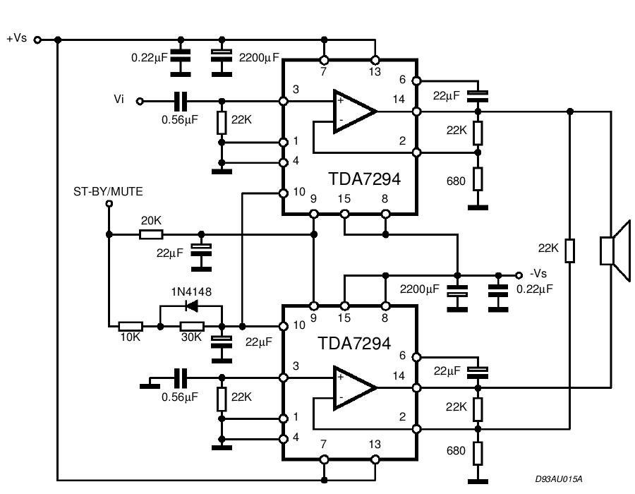
The TDA integrated circuit series is highly regarded and widely utilized in amplifier designs and projects. TDA audio amplifier circuits are primarily produced by Philips and SGS-THOMSON. The most commonly used ICs include the TDA2030 and TDA2003 for small...
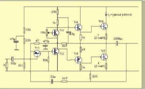
The table below illustrates the expected voltages when utilizing a 24V supply, with the variable resistor adjusted to provide an output current of approximately 40mA. The circuit operates with a 24V DC power supply, where a variable resistor (also known...
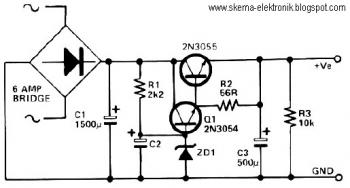
This circuit can be utilized in applications requiring high current and low ripple voltage, such as in high-powered Class AB amplifiers where high-quality audio reproduction is essential. Q1 and Q2, along with resistor R2, function as a power Darlington...
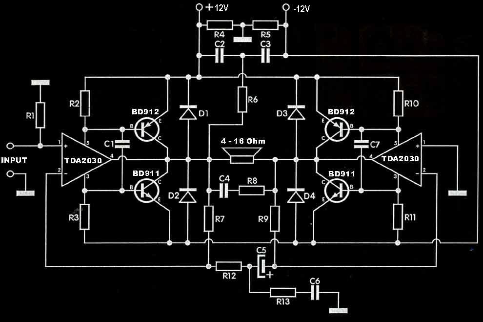
The TDA2030 amplifier circuit is suitable for driving low-frequency subwoofer speakers in home theater systems. The TDA2030 is a monolithic integrated circuit designed for use as a low-frequency class AB amplifier. This TDA2030 amplifier design requires a dual power...