
10w audio amplifier
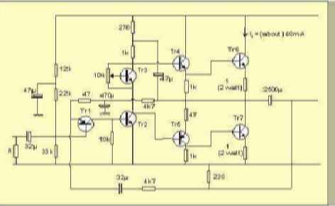
The circuit operates with a 24V DC power supply, where a variable resistor (also known as a potentiometer) is employed to control the current flowing through the output stage. The output stage is designed to deliver a current of about 40mA, which is a critical parameter for ensuring the proper operation of connected components, such as LEDs or other low-power devices.
In this configuration, the variable resistor allows for fine-tuning of the output current by altering the resistance in the circuit. As the resistance is adjusted, the voltage drop across the variable resistor changes, which in turn affects the voltage present at the output. This relationship can be described by Ohm's Law (V = IR), where the voltage (V) across the resistor is equal to the current (I) flowing through it multiplied by the resistance (R).
It is essential to monitor the voltages at various points in the circuit to ensure that they remain within acceptable limits, particularly when the variable resistor is adjusted. The expected voltages can be tabulated based on the resistance settings of the variable resistor, providing a clear reference for users to understand how the adjustments will influence the output current and voltage.
In practical applications, this circuit can be utilized in various electronic devices where precise current control is required, such as in lighting applications, motor speed control, or audio signal processing. Proper design considerations should be taken into account, including the power ratings of the components used and the thermal management of the circuit to prevent overheating during operation.The table below shows the approximate voltages to be expected when using a 24v supply and with the variable resistor set to give a current of about 40mA in the output stage. 🔗 External reference
Related Circuits
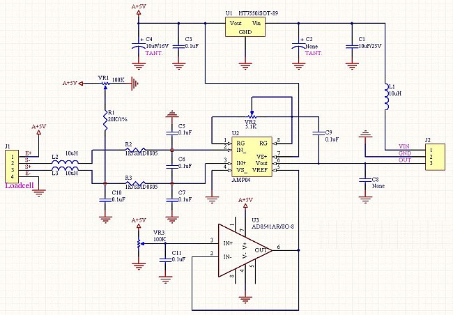
The following circuit illustrates the AD854 integrated circuit used in a load cell amplifier circuit diagram. Features include a 6V gel cell battery charger and a 5V regulated solar cell. The AD854 is a precision, low-power operational amplifier (op-amp) that...
The JBL "Bass Wave" amplifier is a compact 100-watt amplifier featuring a built-in active filter that includes a single-pole high-pass filter at 10 Hz and a single-pole low-pass filter at 85 Hz. Priced at an affordable $50 USD, it...
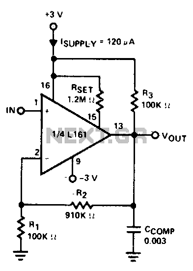
The amplifier is 3 dB down at 100 kHz and has a slew rate of 0.02 V/µs. The amplifier's performance characteristics indicate that it experiences a 3 dB attenuation at a frequency of 100 kHz. This specification suggests that at...
This circuit diagram represents a microphone preamplifier, specifically designed to prioritize voice signals over other audio inputs. In its basic configuration, the circuit includes a microphone unit and a change-over switch that connects to an amplifier. When the push-to-talk...
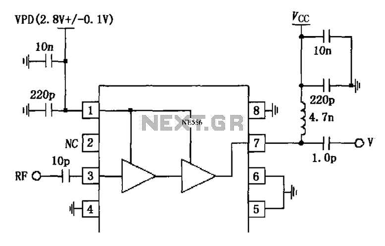
The circuit is constituted by the RF2324 1880MHz internal amplifier collector bias application. A radio frequency (RF) signal enters through input pin 3 and is processed by a preamplifier. The final stage power amplifier output is amplified by 7...
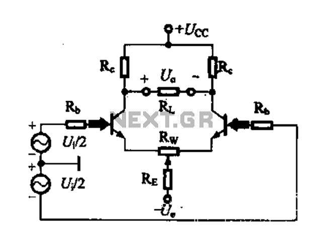
A differential amplifier circuit can be configured in four different connection methods, allowing for a comparison of characteristics such as gain and common-mode rejection ratio (CMRR). This analysis focuses on symmetrical circuits and their performance in handling common-mode signals. The...
Warning: include(partials/cookie-banner.php): Failed to open stream: Permission denied in /var/www/html/nextgr/view-circuit.php on line 713
Warning: include(): Failed opening 'partials/cookie-banner.php' for inclusion (include_path='.:/usr/share/php') in /var/www/html/nextgr/view-circuit.php on line 713