
450W Power Factor Controller with Universal Input Voltage Range

The power factor controller is designed to improve the efficiency of electrical systems by minimizing the phase difference between voltage and current. This is achieved through the use of a specialized integrated circuit (IC) that regulates the power factor. The MC34262 IC is a key component of this design, providing the necessary control and feedback mechanisms to optimize performance.
The schematic diagram typically includes input voltage connections, output load connections, and various passive components such as resistors, capacitors, and inductors that work in conjunction with the IC to filter and smooth the input waveform. The circuit may also incorporate feedback loops to monitor the output voltage and current, allowing for real-time adjustments to maintain an optimal power factor.
The option to replace the MC34262 with the MC33262 offers flexibility in applications that may require operation in more extreme temperature environments. This adaptability is crucial for installations in regions with high ambient temperatures or in industrial settings where environmental conditions can vary significantly.
Overall, this power factor controller design is suitable for a wide range of applications, including residential, commercial, and industrial settings, where power efficiency is a critical concern. The ability to handle a variety of input voltages and loads makes it a versatile solution for improving energy usage and reducing electricity costs.This power factor controller accept voltage from 90 to 268 Vac, that`s why we call it power factor controller with universal input, since any standards of mains supply in almost any country would fall within that range. This power factor controller is capable of handling up to 450W load. Here is the schematic diagram of the power factor controller circuit: Don`t think this circuit is complex because most of what you see in the schematic diagram is the internal circuitry of MC34262 power factor controller integrated circuit chip. You can replace the IC with MC33262 for higher operating ambient temperature range, -40 to 105 Celsius degree, much better then MC34262 chip that has the ambient operating temperature range of 0-85 Celsius degree.
🔗 External reference
Related Circuits
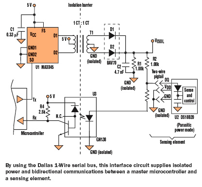
Medical and industrial applications often require galvanic isolation of 2500 V AC or higher for the safety of patients and equipment operators. The isolation barrier conveys not only power to the sensing element but also data to or from...
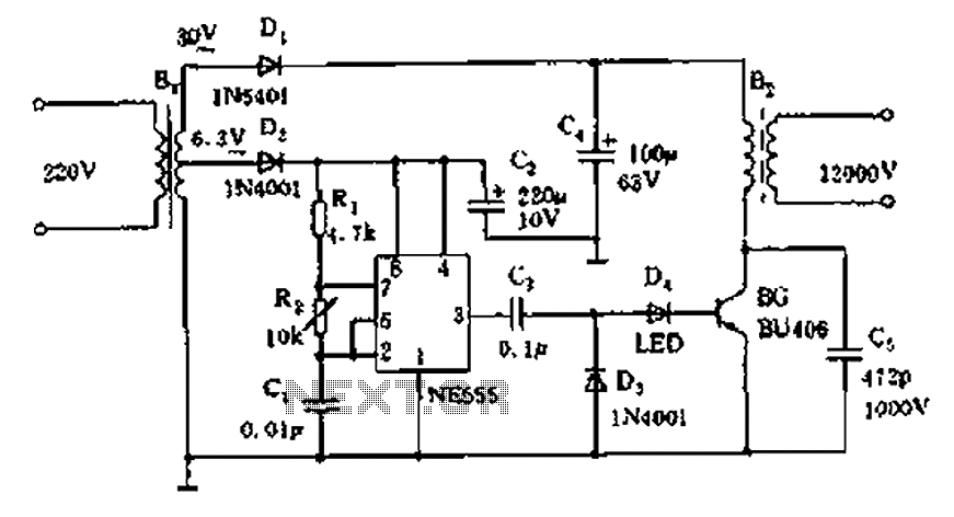
The neon voltage power supply circuit is straightforward to construct, offering stable output power and other desirable characteristics. The core component of this circuit is the NE555 timer, which generates a high-frequency oscillation signal in the range of 15...
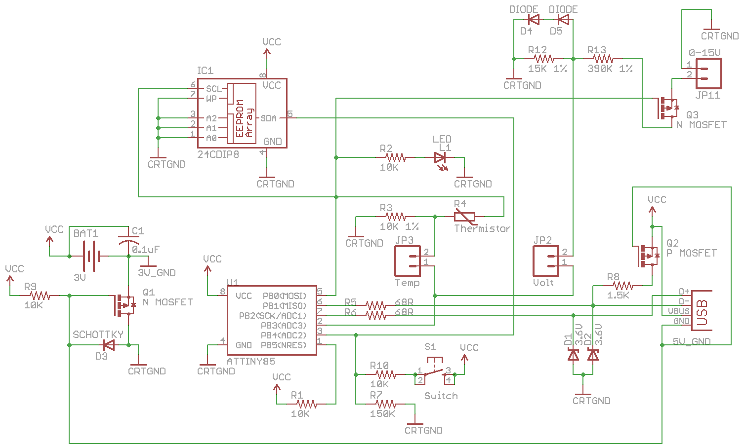
Combine the SATL and SAVL together. The schematic was updated with the voltage sensing circuit. A MOSFET was added to draw power from the voltage source only when needed. There are two jumpers, Temp and Volt, allowing the user...
40V regulated power supply based on TIP42A and LM317. Refer to the specified page for an explanation of the related circuit diagram. The 40V regulated power supply utilizes a TIP42A transistor and an LM317 voltage regulator to provide a stable...
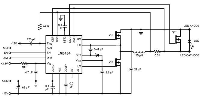
The LM3434 adaptive constant on-time DC/DC buck (step-down) constant current controller can be used to design a simple high-power LED driver application. The LM3434 provides a constant current for illuminating high-power LEDs. The output configuration allows the anodes of...
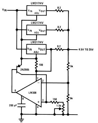
The LM317HV adjustable regulator is capable of supplying over 1.5A across an output voltage range of 1.2V to 57V. The design of this high current power supply is straightforward, as the LM317HV requires only a few external resistors to...