
2G—22W Stereo Car Audio Amplifier schematic diagram

The stereo audio amplifier circuit utilizes the TDA1553CQ integrated circuit, which is a robust solution for automotive audio systems. This IC is designed to deliver high-quality sound output while ensuring efficient power usage. The 22 W output power per channel is adequate for driving car speakers, providing clear and powerful audio reproduction.
The TDA1553CQ features a BTL (Bridge-Tied Load) configuration, which allows for enhanced output power by effectively doubling the voltage across the load, resulting in improved audio performance. The two identical amplifiers within the IC are equipped with differential input stages, ensuring minimal noise and distortion, which is critical in automotive environments where electromagnetic interference can be prevalent.
The fixed gain of 26 dB simplifies the design process, as it eliminates the need for external gain-setting components, thus streamlining the overall circuit design. The integration of the amplifier in a single package reduces the number of external components needed, contributing to a more compact and efficient design.
To implement this circuit, it is essential to consider the power supply requirements, as well as proper thermal management, to ensure reliable operation under varying conditions. Additionally, appropriate filtering capacitors and decoupling measures should be included to maintain audio fidelity and prevent power supply noise from affecting the output.
Overall, the TDA1553CQ stereo audio amplifier circuit represents a practical solution for enhancing car audio systems, combining efficiency, power, and sound quality in a single integrated package.This is a schematic diagram of stereo audio amplifier for your car. The circuit is powered by a single IC TDA1553 with some external components, this IC will handle your stereo car audio system. The TDA1553CQ is a monolithic integrated class-B output amplifier in a 13-lead plastic DIL-bent-SIL power package.
It contains 2G—22 W amplifiers in BTL c onfiguration. The device is primarily developed for car radio applications. The TDA1553CQ contains two identical amplifiers with differential input stages and can be used for bridge applications. The gain of each amplifier is fixed at 26 dB. 🔗 External reference
Related Circuits
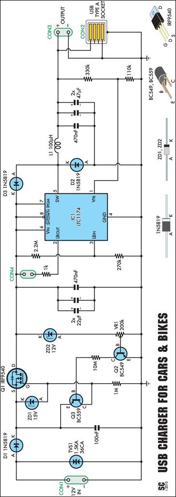
An efficient USB charger designed to operate from a 12V car battery, achieving up to 89% efficiency and capable of charging USB devices at currents up to 525mA. It does not drain the battery if left permanently connected, provided...

This circuit is designed as a pocket-sized, high-performance audio oscillator. It can operate using a battery-powered version, which is feasible at a very low cost by utilizing a single quad op-amp to provide the entire active circuitry. The design...

This design circuit functions to filter out interference signals, ensuring that the signal received from a Morse code station is distinct. The circuit utilizes the earliest mode of radio communications, which employs Morse Code on a continuous wave carrier...
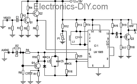
This TV transmitter transmits audio and video signals from camcorders, DVD players, VHS players, satellite systems, video games, etc., broadcasting them on a channel free from the VHF strip. These signals can be radiated using a common antenna and...
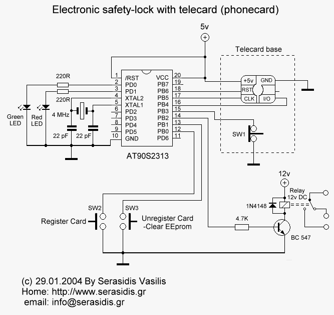
Most of the source code for this project is based on the Telecard reader project from my website. The components are few and ordinary, which means they are low-cost and easy to find. The "keys" are empty or non-telecards...
A car battery deteriorates with use, typically lasting no more than four years. Initially, its voltage may drop to just 2V when cranking the engine. As the battery ages, its internal impedance increases, leading to a higher voltage drop...