
2N2646 Transistor For Flashing LED EGG Timer

The flashing LED egg timer circuit operates as a visual timer, providing an indication of elapsed time through the blinking of an LED. The core components of this circuit include the 2N2646 transistors, which serve as the primary switching elements, and the MPF112 FET, which is used for signal amplification and control within the circuit.
The circuit is designed to produce a periodic flashing effect, which can be adjusted based on the resistor and capacitor values used in the timing section. The timing mechanism typically consists of an RC network that charges and discharges, controlling the base current of the 2N2646 transistors. When the capacitor reaches a certain voltage, it triggers the transistor, allowing current to flow through the LED, causing it to illuminate. As the capacitor discharges, the LED extinguishes, creating a flashing effect.
To ensure proper operation, the circuit should be powered with a suitable voltage source, typically in the range of 5V to 15V, depending on the specifications of the components used. The choice of resistors and capacitors will determine the frequency of the LED flashing, which can be tailored for specific applications, such as kitchen timers or alert systems.
In summary, this flashing LED egg timer circuit effectively combines the use of transistors and FET technology to create a reliable and adjustable timing mechanism, making it a versatile solution for various electronic timing applications.The following circuit shows about Flashing LED EGG Timer Circuit Diagram. This circuit using the 2N2646 transistors. Features: MPF112 FET .. 🔗 External reference
Related Circuits
A LED is defined as "light-emitting diode: diode such that light emitted at a p-n junction is proportional to the bias current; color depends on the material used." As the LED is a diode, it doesn't conduct electricity in...
Typically, an LED is powered by a DC supply; however, this circuit enables the LED to be powered by an AC supply. This circuit can serve as a power indicator for a water pump. The circuit for powering an LED...
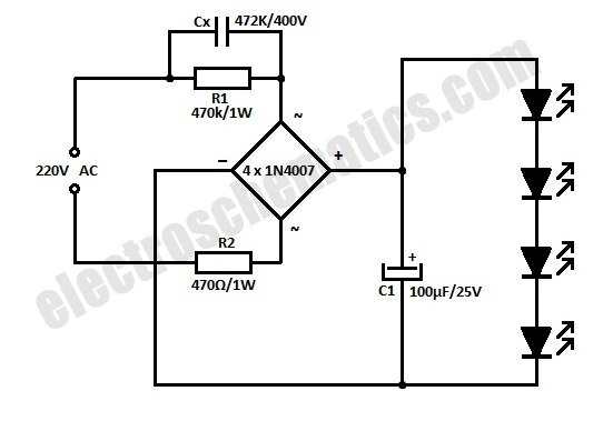
This is a simplified version of a white LED lamp that can be powered directly from the mains. It provides sufficient illumination for reading purposes. Capacitor Cx along... The circuit for the white LED lamp consists of several key components...
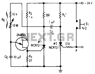
After one cycle of operation, SCR1 will be activated, resulting in a low voltage being applied to the UJT emitter circuit, which interrupts the tuning function. When pushbutton SI is pressed, or a positive pulse is applied at point...
An AM radio receiver can be constructed using only two active components, operating in the Medium Wave (MW) band. The circuit employs a straightforward receiver configuration. The described AM radio receiver circuit leverages a minimalist approach by utilizing just two...

Manufacturers of cordless drills typically recommend a battery charging time of three hours. Once this charging time is complete, the battery must be disconnected from the charger to prevent the risk of overcharging. This circuit, positioned between the charger...