
AC-Powered LED
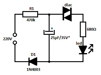
The circuit for powering an LED using an AC supply typically involves a few key components to ensure proper functionality and safety. The main components include a diode bridge rectifier, a current-limiting resistor, and the LED itself.
The diode bridge rectifier converts the alternating current (AC) input into direct current (DC). This is crucial because LEDs require a unidirectional flow of current to operate effectively. The rectifier consists of four diodes arranged in a bridge configuration, allowing both halves of the AC wave to be utilized, thus providing a smoother DC output.
Following the rectifier, a current-limiting resistor is employed to prevent excessive current from flowing through the LED. The resistor value can be calculated using Ohm's law, taking into account the forward voltage drop of the LED and the peak voltage output from the rectifier. This ensures that the LED operates within its specified current range, prolonging its lifespan and maintaining optimal brightness.
The LED serves as the visual indicator, illuminating when power is supplied to the circuit. The entire assembly can be integrated into the power supply line of a water pump, providing a clear indication of operational status. This setup is particularly useful in applications where monitoring the power status of a water pump is essential for maintenance and operational efficiency.
In summary, this circuit effectively allows an LED to function with an AC supply, making it a practical solution for power indication in water pump applications. Proper selection of components and adherence to electrical safety standards are critical to ensure reliable and safe operation.Usually, LED is powered by DC supply, but this circuit can make the LED can be powered by AC supply. This circuit can be used as power indicator for Water pump.. 🔗 External reference
Related Circuits

The Spartan-6 board features 16 LEDs connected to FPGA I/O pins, as detailed in the table below. The cathode of each LED is connected to ground through a 330-ohm resistor. To illuminate a specific LED, the corresponding FPGA control...

The simple indicator described in this article can be integrated with any circuit that features an LED bar display powered by a Type LM3914 IC. It ensures that an LED will illuminate when all LEDs driven by the LM3914...
This is likely the simplest concept for generating a flashing light from an LED using alternating current (AC). The circuit provides a straightforward method for flashing one or more LEDs using high-voltage direct current (DC) sourced from mains electricity....

This is a low power voltmeter circuit designed for use with alternative energy systems that operate on 12V and 24V batteries. The voltmeter features an expanded scale that indicates small voltage steps within the 10 to 16 volt range...

The CA3080 can be utilized as a gain-controlling device. The input signal is attenuated by resistors R1 and R2 so that a 20 mV peak-to-peak signal is applied to the input terminals. If this voltage exceeds a certain threshold,...
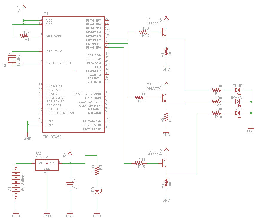
A very popular type of LED that has finally emerged is the tri-color, RGB LED. The RGB stands for red, green, and blue, as the LED is capable of displaying various colors through the combination of these three primary...
Warning: include(partials/cookie-banner.php): Failed to open stream: Permission denied in /var/www/html/nextgr/view-circuit.php on line 713
Warning: include(): Failed opening 'partials/cookie-banner.php' for inclusion (include_path='.:/usr/share/php') in /var/www/html/nextgr/view-circuit.php on line 713