
2x10 Band Stereo Graphic Equaliser

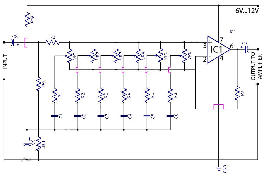
The 20-band stereo graphic equalizer circuit comprises multiple filter stages, each corresponding to a specific frequency band. The primary function of this equalizer is to adjust the amplitude of audio signals across these bands, allowing for enhanced control over the sound output. Typically, each band is centered around a specific frequency, with the equalizer enabling boosts or cuts to the signal levels as required by the user.
The circuit generally includes a series of band-pass filters, operational amplifiers for signal processing, and potentiometers for user control. Each band-pass filter is tuned to a specific frequency, allowing for precise adjustments in the audio spectrum. The operational amplifiers amplify the filtered signals, ensuring that the output maintains a strong and clear audio quality.
In a typical configuration, the input audio signal is fed into the circuit, where it is split among the various filter stages. Each stage processes the signal corresponding to its designated frequency band. The user can manipulate the potentiometers to either increase or decrease the gain of each band, thus shaping the overall sound profile.
After processing, the combined output from all frequency bands is sent to the amplifier circuit. It is crucial that the equalizer circuit is placed before the amplifier to prevent distortion and to ensure that the amplifier receives a properly balanced signal.
For optimal performance, it is essential to consider component selection, including high-quality capacitors and resistors, to minimize signal degradation. Additionally, careful layout design can help reduce noise and interference, further enhancing the performance of the equalizer circuit. Proper grounding techniques should also be employed to maintain signal integrity throughout the audio processing chain.The following diagram is the circuit diagram of 20 band stereo graphic equaliser which will controlling the audio signal in specific frequency range. This circuit must be connected before the amplifier circuit. For maximum performance, you.. 🔗 External reference
Related Circuits
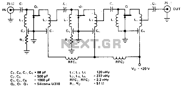
The amplifier circuit is designed for a center frequency of 225 MHz, with a bandwidth of 50 MHz at 1 dB, low input voltage standing wave ratio (VSWR) in a 75-ohm system, and a gain of 24 dB. Three...
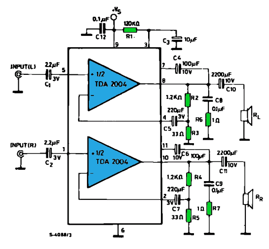
The TDA2004 integrated circuit (IC) is a popular choice among audio electronics enthusiasts due to its affordability and availability. This IC is often utilized in audio amplifier designs because it features two outputs and inputs, making it easy to...
Figure (a) illustrates a general inverting amplifier circuit, which includes a 100k potentiometer as a feedback resistor connected in series between the input terminal and the inverting input to compensate for the DC bias current. The potentiometer (Rp) should...
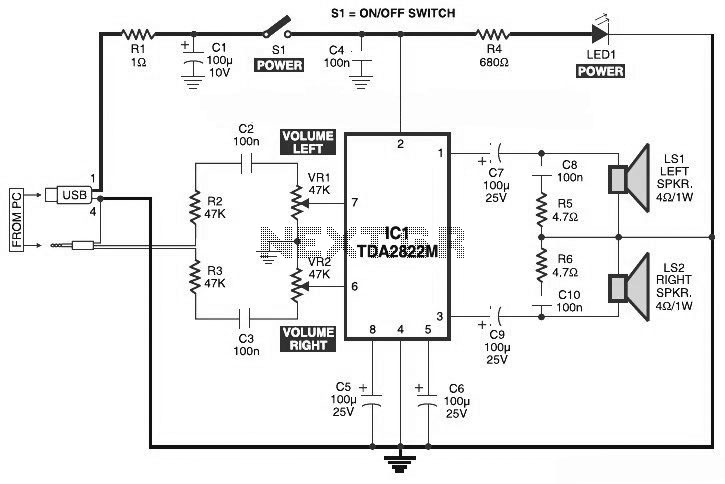
This is the circuit diagram of a USB-powered computer speaker, commonly known as multimedia speakers for PCs. The circuit features a single-chip design, operates on a low-voltage power supply, and is compatible with USB power from a computer. The USB-powered...
This circuit is a six-band graphic equalizer that allows modification of sound across low, mid, and high frequencies using an IC 741 operational amplifier. It enables management and mixing of frequencies and tones as desired. The audible frequency spectrum...
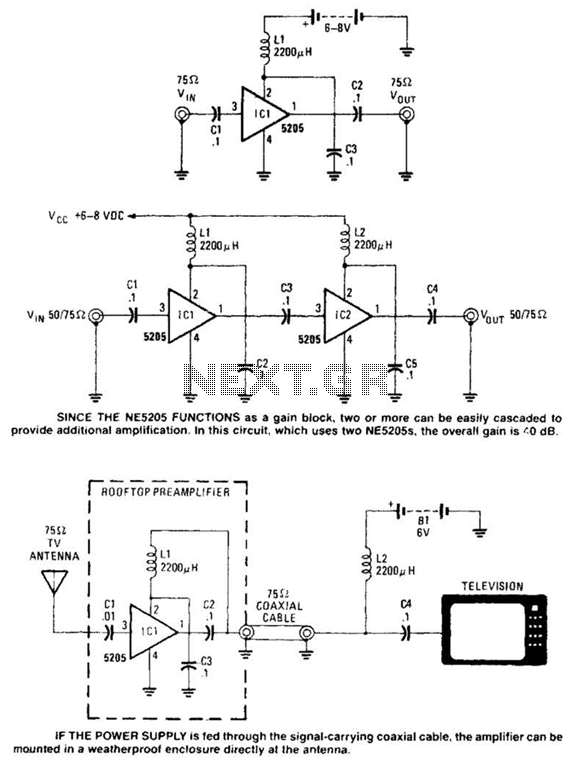
Except for the coupling and decoupling capacitors, IC1 is a complete wideband amplifier that has a fixed gain of 20 dB up to 450 MHz. No external compensation is required. Since the NE5205 functions as a gain block, two...