
USB Powered Stereo Computer Speaker

The USB-powered computer speaker circuit is designed to efficiently convert the USB power supply into audio output suitable for multimedia applications. The circuit typically includes a single integrated circuit (IC) that serves as both the amplifier and the audio processing unit. This design minimizes component count and reduces the overall size of the speaker system, making it ideal for portable and desktop use.
The power supply from the USB port provides a nominal voltage of 5V, which is sufficient for driving small speakers. The circuit may include a voltage regulator to ensure stable operation and prevent fluctuations that could affect audio quality. Additionally, capacitors are employed to filter out noise and stabilize the power supply.
The audio input is usually taken from the computer's audio output, which can be connected via a standard 3.5mm jack. The circuit may also feature an onboard volume control, allowing the user to adjust the sound level conveniently. Output transistors or additional amplification stages may be included to drive the speaker drivers effectively, ensuring clear and loud sound reproduction.
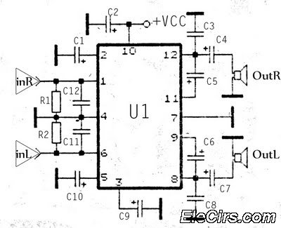
In summary, the USB-powered computer speaker circuit is a compact and efficient solution for multimedia audio output, leveraging a single-chip design for simplicity and ease of integration with computer systems.This is the circuit diagram of USB powered computer speaker, or it widely known as multimedia speakers for PCs. The circuit has single-chipbased design, low-voltage electrical power supply, compatibility with USB power from computer, simple..
🔗 External reference
Related Circuits
The PIC16C57-RCT is a communication single-chip microcomputer integrated circuit that is commonly utilized in the Qiao Xing series of IC card management telephones. The PIC16C57-RC integrated circuit features a pulse and dual-tone dialing circuit, memory data and clock circuit,...
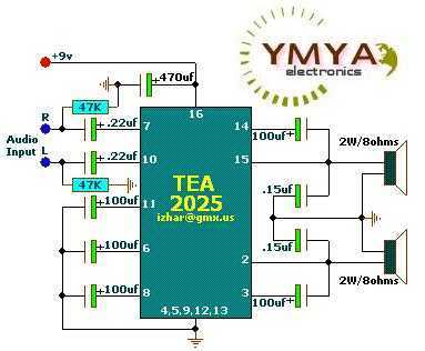
These circuits are based on TEA2025, a monolithic integrated audio amplifier in a 16-pin plastic dual in-line package manufactured by UTC. The circuit includes an internal thermal protector and is designed for portable cassette players and radios. It can...
This circuit is designed to produce square waves by converting a sine wave obtained from an existing generator. A key feature is that it requires no external power source, allowing for simple connection between a sine wave generator and...
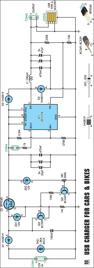
An efficient USB charger designed to operate from a 12V car battery, achieving up to 89% efficiency and capable of charging USB devices at currents up to 525mA. It does not drain the battery if left permanently connected, provided...
The KA2211 stereo audio power amplifier schematic is designed for electronics applications. This amplifier circuit provides a stereo output with a power output of 2 x 5.8 Watts at an impedance of 4 ohms. The frequency response ranges from...
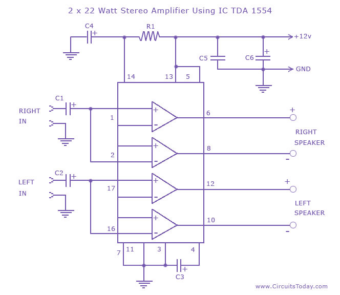
A high-quality stereo amplifier circuit of 44 Watts (22 Watts per channel) using the TDA 1554 IC. This is a powerful audio amplifier circuit for 2 channels. The described stereo amplifier circuit utilizes the TDA 1554 integrated circuit (IC), which...