
2x20 Watt Stereo Power Amplifier

The circuit described utilizes the TDA2050 integrated circuit, which is a high-performance audio amplifier designed for various applications, including home audio systems and automotive sound systems. The TDA2050 operates efficiently with a power supply voltage typically ranging from 12V to 35V, making it suitable for a variety of power amplifier designs.
The schematic includes a feedback resistor (R4) set to 22kΩ, which establishes a voltage gain of 27dB. This gain can be adjusted by changing the value of R4; however, care must be taken to ensure that the gain does not fall below 10 (20dB) as determined by the feedback network formed with R5. This is crucial to maintain the stability and performance of the amplifier, preventing distortion and ensuring a clean output signal.
The circuit layout is optimized for use on a printed circuit board (PCB), which facilitates the construction and minimizes the potential for noise and interference that can occur when using a perfboard or Veroboard. The pin configuration of the TDA2050 is designed for straightforward integration into the circuit, allowing easy connections for input, output, power supply, and ground.
In terms of additional components, bypass capacitors may be included near the power supply pins to filter out noise and stabilize the voltage supply. Output coupling capacitors can also be employed to block any DC offset from the output, ensuring that only the AC audio signal is passed to the speakers.
Overall, this amplifier design is characterized by its simplicity and effectiveness, making it an excellent choice for audio amplification projects. Proper attention to component selection and circuit layout will yield a reliable and high-quality audio amplifier.This project is based almost directly on the typical application circuit in the National Semiconductor specification sheet. You can also use the TDA2050 (from SGS-Thompson), which has almost identical performance and (remarkably) the same pinouts!
As it turns out, the amp in the NS application circuit is pretty good, as is the (very similar) one from SGS. The amp is also remarkably simple to build - if you have a PCB! These ICs are a cow to wire on Veroboard - it is possible, but results are unpredictable. Voltage gain is 27dB as shown, but this can be changed by using a different value resistor for the feedback path (R4, currently 22k, between pins 2 and 4). The amplifier must not be operated at any gain less than 10 (20dB) as set by R4 and R5, as it will 🔗 External reference
Related Circuits
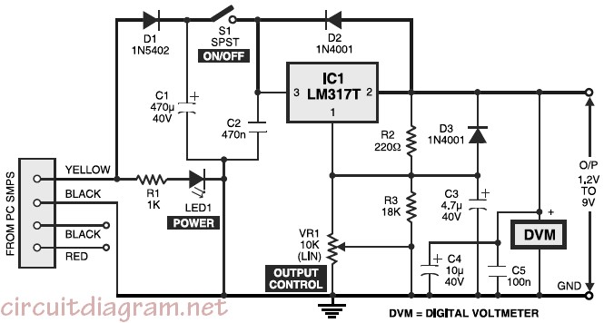
Variable desktop power supply that converts a high input voltage (12V) from the SMPS/PSU of a desktop computer into a small output voltage (1.25V to 9V). The variable desktop power supply is designed to provide adjustable output voltages ranging from...
A simple solenoid driver utilizes incandescent lamp filaments as on-indicators to limit power consumption. High magnetic reluctance in the coil of an armature-driven device, such as a solenoid or relay, requires a surge of activation current, followed by a...
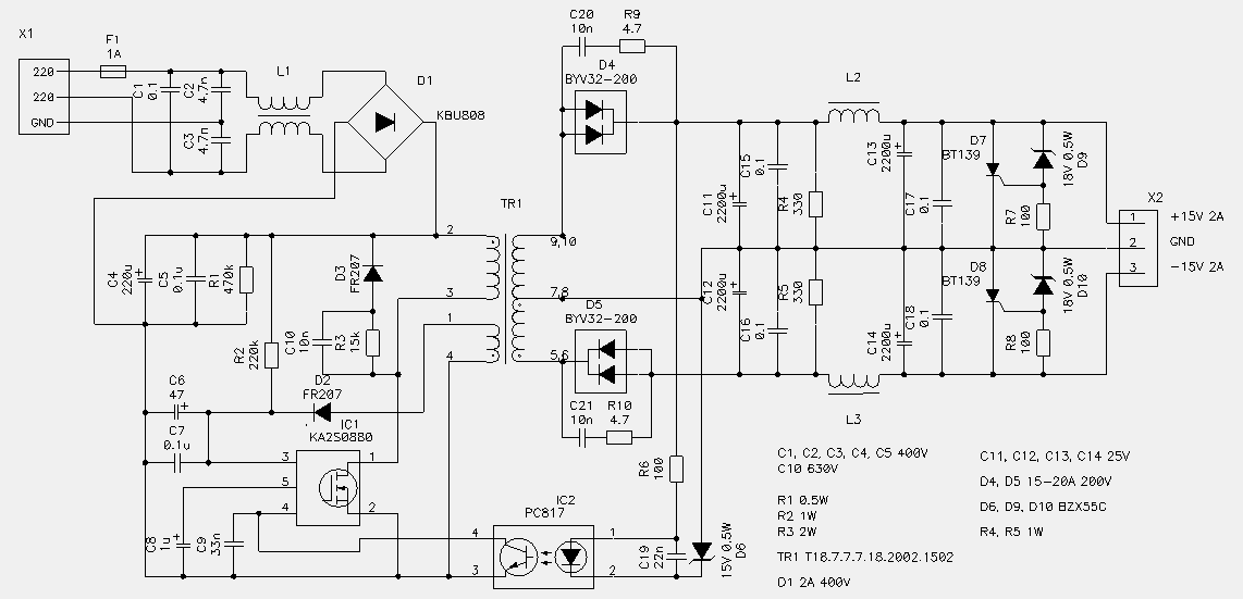
70 W switching power supply utilizing the KA2S0880 integrated circuit. Refer to the specified page for an explanation of the associated circuit diagram. The 70 W switching power supply designed with the KA2S0880 integrated circuit (IC) is a versatile solution...
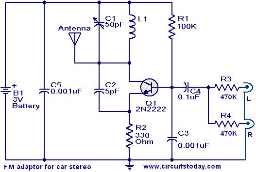
This compact FM adapter circuit, when connected to the audio output of a cassette player or iPod, enables the user to listen to their favorite music through a car stereo. It is particularly useful for vehicles that lack an...
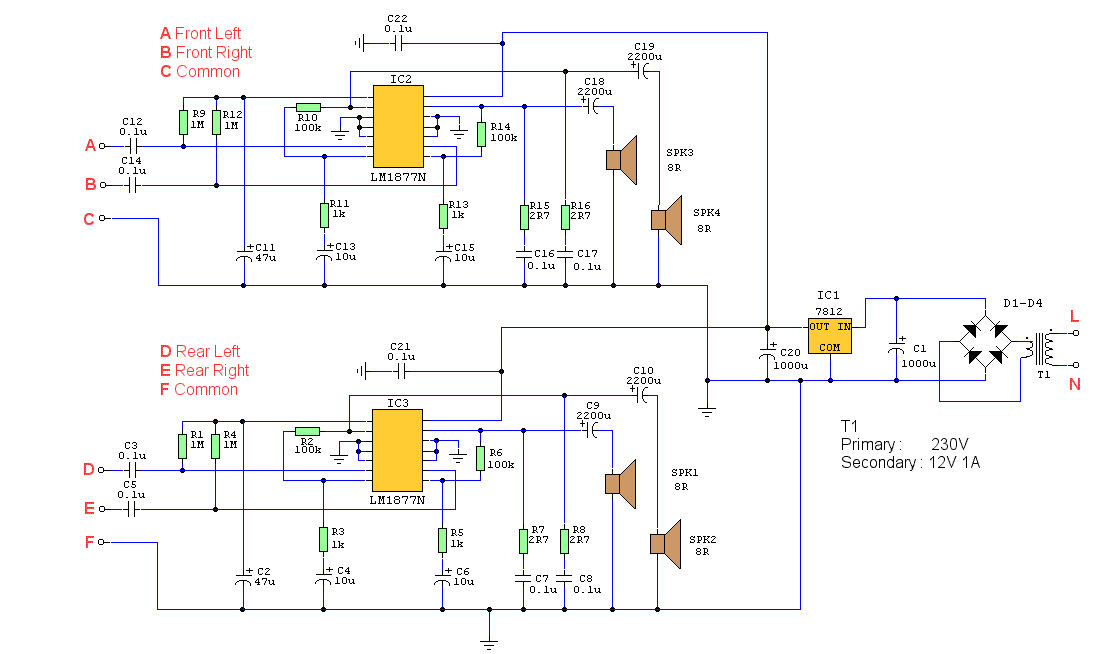
This is a four-channel amplifier designed for use with quadraphonic equipment, such as a Sound Blaster Live card. There is no volume control; audio levels are managed directly by the sound card. The construction is straightforward and suitable for...
This circuit utilizes a tricolor LED display to signify acceptable and unacceptable output voltages. One LED indicates the upper voltage limit, while another indicates the lower voltage limit. When the monitored voltage exceeds the maximum set point, the LED...