
Power supply monitor
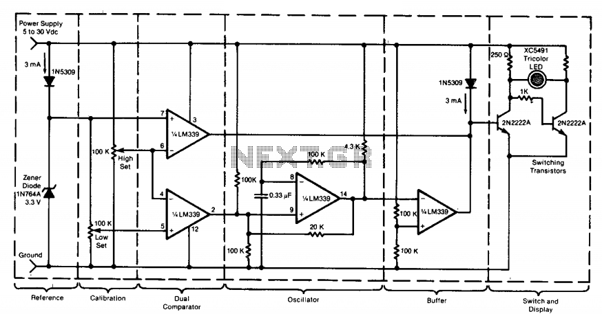
The described circuit employs a tricolor LED display, which serves as a visual indicator for voltage levels in a monitored system. The circuit includes voltage reference points, typically set using potentiometers, to define the upper and lower voltage thresholds. These reference points are compared against the monitored voltage via a microcontroller or comparator circuit.
The green LED indicates normal operating conditions, lighting up when the monitored voltage is within the defined range. The red LED activates when the voltage exceeds the upper limit, signaling a critical condition that requires immediate attention. Conversely, the yellow LED serves as an alert for voltages that fall below the lower limit, indicating potential system failure or malfunction.
The circuit's design allows for flexibility in application; it can be configured to monitor voltage levels for a single power supply or to compare two different voltages. In the latter case, additional components such as differential amplifiers may be utilized to accurately measure the voltage difference. The alarm system can be implemented using simple buzzer circuits or more sophisticated sound modules, depending on the required alerting mechanism.
For remote monitoring capabilities, the circuit can incorporate wireless transmission modules, such as Wi-Fi or Bluetooth, enabling real-time feedback to an operator's device. This feature enhances system oversight, especially in industrial environments where immediate responses to voltage fluctuations are crucial.
Overall, the circuit's ability to operate without an external power supply, combined with its adaptability for various monitoring scenarios, makes it a versatile tool in electronic applications.This circuit uses a tricolor LED display to indicate acceptable and unacceptable output voltages. One to set the upper voltage limit, the other, the lower voltage limit. When the monitored voltage is above the set maximum, the LED display turns red. Yellow turns On for voltages below the set minimum, and green turns on for voltages between the high and the low settings. The circuit does not need a separate power supply. It is powered by the voltage it monitors. The circuit can be adapted to monitor voltage differences between two power supplies. Should the monitored voltages differ by more than a set value, a visual or an audible alarm would warn the operator about the difference. The circuit can also be modified for remote monitoring and the use of a separate power supply. 🔗 External reference
Related Circuits
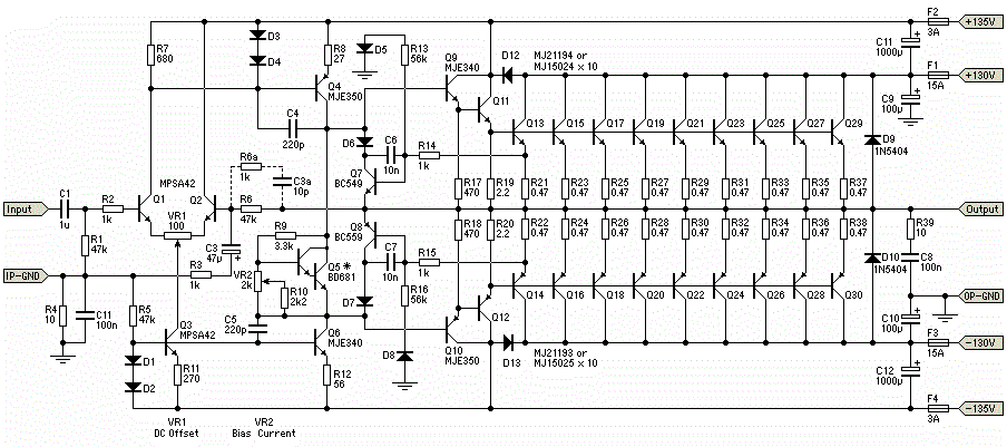
The circuit for the power amplifier has a power output of up to 1500W RMS and is commonly utilized in outdoor sound systems. The final image displays a series of power amplifiers that utilize 10 sets of power transistors....
This guide demonstrates how to construct a detachable solar panel and battery charger suitable for a backpack. It is designed to power or charge various electronic devices. The project involves integrating a solar panel with a rechargeable battery system that...
Cold Cathode Fluorescent Lamps (CCFLs) are commonly employed to illuminate the LCD displays of portable computers. These lamps necessitate a high-voltage sine-wave drive. The circuit designed for this purpose provides such a drive and allows for the continuous and...
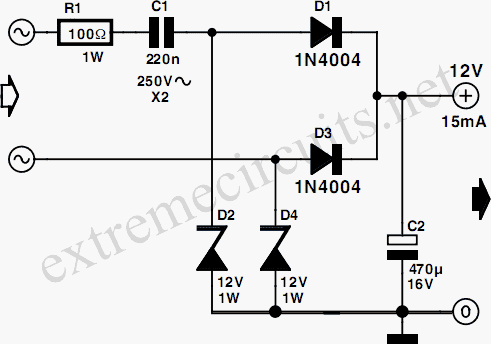
Many circuits can be powered directly from the mains with the aid of a series capacitor (C1). The disadvantage of this approach is that usually only one half cycle of the mains waveform can be used to produce a...

Designing a power supply that meets the requirements of Power over Ethernet (PoE) and Voice over Internet Protocol (VoIP) applications can be complex. The low-component-count power supply illustrated in the figure complies with these specifications without requiring intricate circuitry....
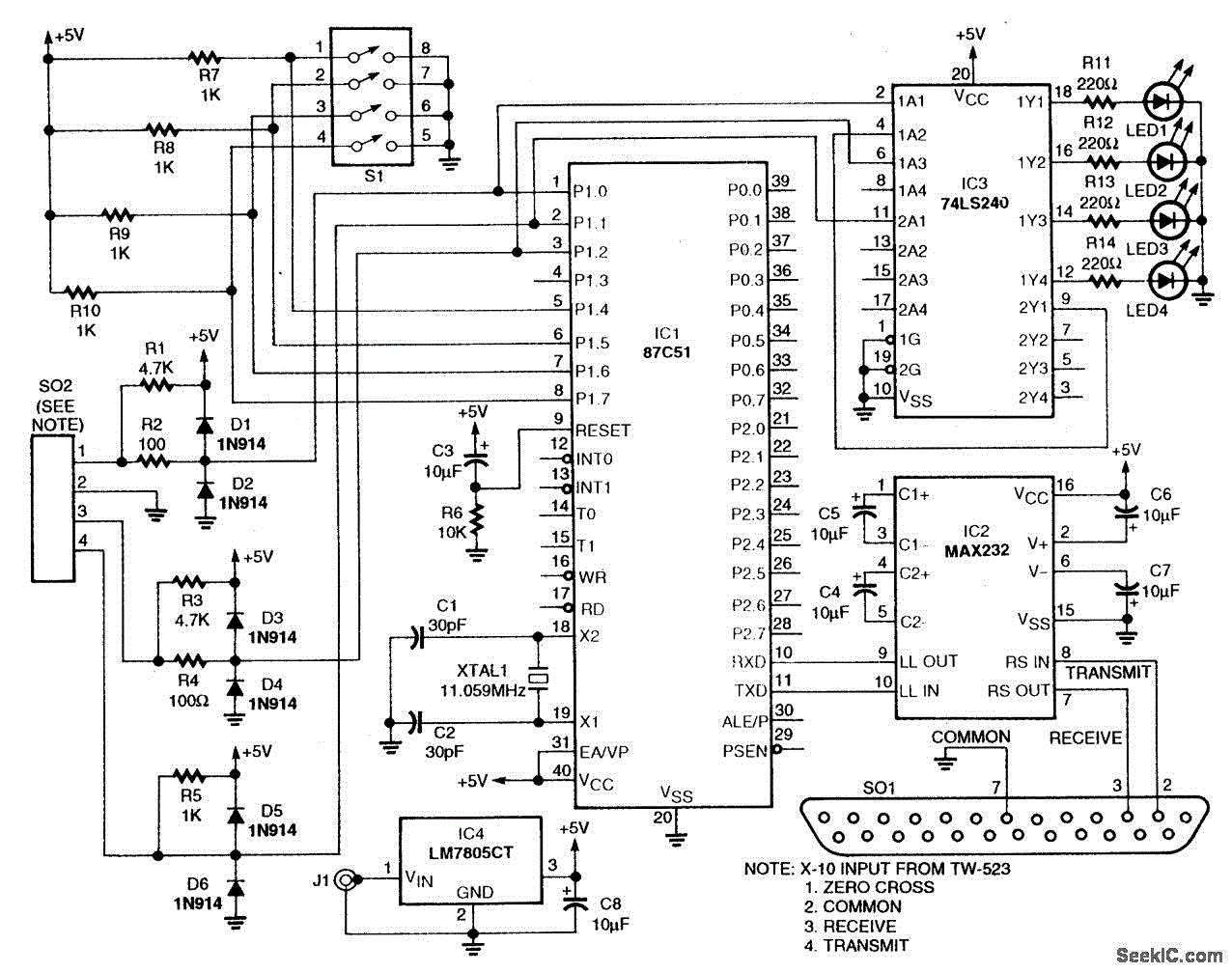
This circuit employs an 87C57 microcontroller along with several peripherals to convert X-10 power-line carrier-code formats from a personal computer for use with an X-10 power-line interface in a home-control system. Software details can be found in the reference. The...