
FM adaptor circuit for car stereo
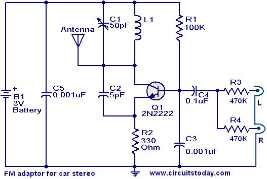
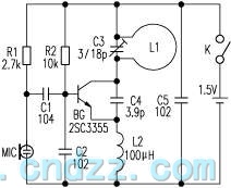
This FM adapter circuit is designed to facilitate audio transmission from portable devices to car stereos, enhancing the listening experience for users without direct auxiliary input options. The core of the circuit is the 2N2222 NPN transistor, which operates as the primary amplifying component. The tank circuit, formed by inductor L1 and capacitor C1, is crucial for generating the radio frequency oscillations necessary for FM transmission. The resonant frequency is determined by the values of L1 and C1, and careful selection of these components can optimize performance for specific frequency bands.
The mixing stage of the circuit is achieved through the combination of capacitors C4 and resistors R3 and R4, which blend the audio signals from the device into a format suitable for transmission. This mixing process ensures that the sound quality remains high and that stereo signals are preserved, providing an enjoyable listening experience.
Stability in the circuit is maintained by the emitter resistor R2, which plays a dual role. It not only stabilizes the transistor's operation but also limits the current flowing through the collector. This current limitation is vital for prolonging battery life, especially in portable applications where power efficiency is a priority.
Overall, this FM adapter circuit represents an effective solution for integrating modern audio devices with older car stereo systems, providing flexibility and convenience for users seeking to enjoy their music on the go.With this compact FM adaptor circuit plugged into the audio out of your cassete player or i Pod out put, you can listen your favorite music on your car stereo. This circuit is very useful if your car stereo doesnot have an auxillary in socket. The circuit is nothing buy an short range FM transimitter. The FM transmitter circuit is based on low power NPN transistor 2N2222. The tank circuit consisting of L1 & C1 producess the necessary oscillations at the collector of Q1. The capacitance C4, resistance R3 & R4 performs the function of mixing the stereo out put from theaudio player or i-Pod. The emitter resistance R2 provides sufficient stability to the circuit. It also limits the collector current to increse the battery life. 🔗 External reference
Related Circuits
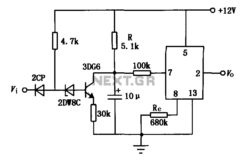
The delay application circuit is depicted in Figure JEC-2, which consists of two components. When the input transitions from logic level 0 to 1, the output also changes to 1 immediately. However, when the input transitions from high level...
This file is copyrighted. The individual who uploaded this work and first used it in licensing holds the rights. The provided information indicates that the file is protected by copyright, with the rights belonging to the individual who initially uploaded...
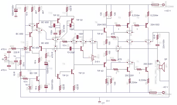
This post presents the circuit schematic diagram for a 500-watt mono power amplifier. As of July 18, 2012, the intention is to create a power sound system with a total output of 1000 watts in stereo. The design utilizes...
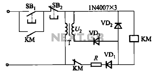
An AC contactor DC transformer circuit operates as a voltage regulator for AC applications. DC contactors come in various types. AC contactors are electromechanical devices used to control the flow of electrical power in AC circuits. They function by opening...
The automatic sprinkler controller circuit consists of a clock timing controller, a monostable flip-flop, a bistable flip-flop, an electronic switch, a self-excited multivibrator, a counter, a solenoid valve control circuit, and a power supply circuit. The power supply circuit...
The loop antenna L1 is utilized for emission and also functions as the oscillation coil. The high-frequency current flowing through the antenna is synchronized in resonance with the oscillation frequency, ensuring optimal emission performance. Practical applications indicate that the...