
3-24V / 3A power supply
This regulated power supply circuit is designed for versatility, allowing output voltage adjustments from 3V to 25V while providing current limiting features. The output current can be set to a maximum of 2A, with the potential to increase to 3A by changing the current sense resistor to a lower value, specifically a 0.3-ohm resistor. The choice of transistors, namely the 2N3055 and 2N3053, is critical as they handle the power amplification and must be adequately cooled using heat sinks to prevent thermal overload.
The voltage regulation is managed by an operational amplifier (op-amp), specifically utilizing either the 1558 or the 1458 model. It is important to note that while the 1458 can be used as a substitute, the supply voltage to pin 8 should not exceed 30VDC. This limitation can be achieved by incorporating a 6.2V zener diode or a 5.1K resistor in series with pin 8, ensuring the op-amp operates within safe voltage parameters.
The power transformer must be selected carefully; it should provide an AC voltage that is at least 4V higher than the desired DC output voltage, while also adhering to the maximum input voltage ratings of the op-amps, which are 36V for the 1458 and 44V for the 1558. A center-tapped transformer rated at 25.2V AC and 2A is recommended for this application, as it can deliver various regulated outputs: 24V at 0.7A, 15V at 2A, and 6V at 3A. The 3A output can be accessed by utilizing the center tap of the transformer with the switch set to the 18V position.
Component sourcing is relatively straightforward, with most parts available from common electronics suppliers, although the 1558 op-amp may require sourcing from specialized vendors. This design is suitable for various applications requiring adjustable and regulated power supplies, making it a valuable addition to any electronics laboratory or workshop.This regulated power supply can be adjusted from 3 to 25 volts and is current limited to 2 amps as shown, but may be increased to 3 amps or more by selecting a smaller current sense resistor (0.3 ohm). The 2N3055 and 2N3053 transistors should be mounted on suitable heat sinks and the current sense resistor should be rated at 3 watts or more.
Voltage regulation is controlled by 1/2 of a 1558 or 1458 op-amp. The 1458 may be substituted in the circuit below, but it is recommended the supply voltage to pin 8 be limited to 30 VDC, which can be accomplished by adding a 6.2 volt zener or 5.1 K resistor in series with pin 8. The maximum DC supply voltage for the 1458 and 1558 is 36 and 44 respectively. The power transformer should be capable of the desired current while maintaining an input voltage at least 4 volts higher than the desired output, but not exceeding the maximum supply voltage of the op-amp under minimal load conditions. The power transformer shown is a center tapped 25.2 volt AC / 2 amp unit that will provide regulated outputs of 24 volts at 0.7 amps, 15 volts at 2 amps, or 6 volts at 3 amps.
The 3 amp output is obtained using the center tap of the transformer with the switch in the 18 volt position. All components should be available at Radio Shack with the exception of the 1558 op-amp. 🔗 External reference
Related Circuits
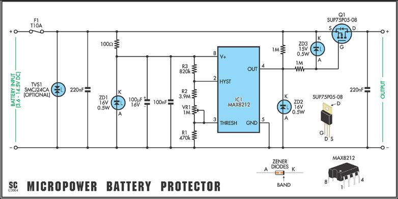
In May 2002, Silicon Chip introduced the "Battery Guardian," a project aimed at safeguarding 12V car batteries from over-discharge. This unit has gained significant popularity and remains available from kit suppliers. The new design does not replace the Battery...
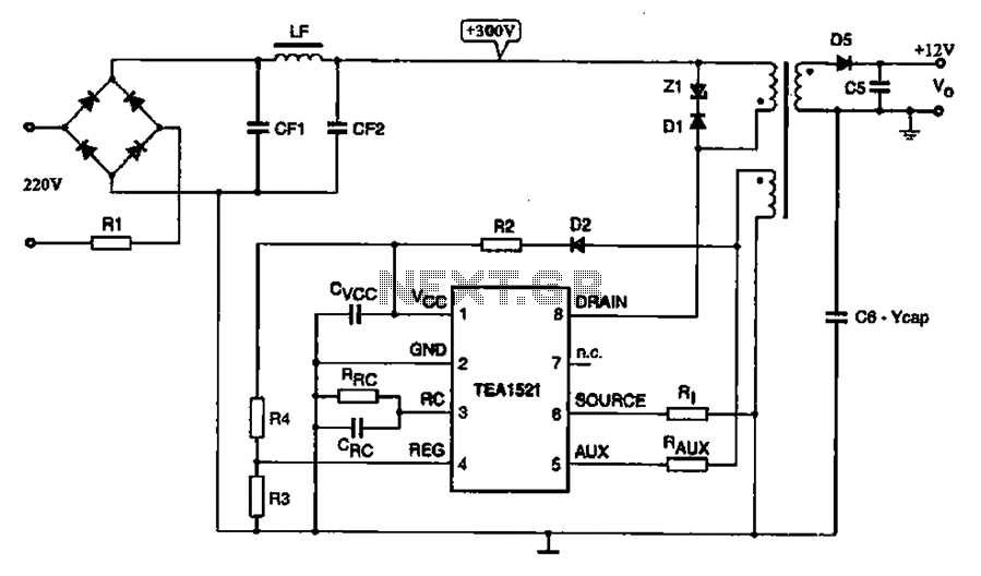
A typical DVD switching power supply circuit is shown in the standby power supply circuit of digital products. It utilizes a switching power supply structure, with the oscillation switch IC EA1623 providing oscillation pulses to the transformer. The secondary...
The ADP1864 is a compact, cost-effective, constant-frequency current-mode step-down DC-DC controller. It drives a P-channel MOSFET to regulate an output voltage as low as 0.8 V with ±2% accuracy, handling load currents up to 5 A from input voltages...
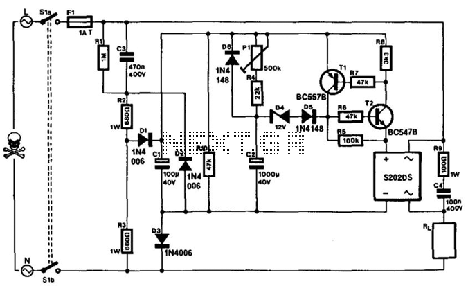
This timer can be integrated into a power line to provide a controllable delay before a load is activated. The mains voltage is reduced by capacitor C3 and rectified to yield approximately 30 V across capacitor C1. This voltage...
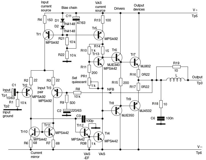
This document discusses the advantages and disadvantages of various power supply technologies, along with the design considerations necessary for selecting and evaluating a mains transformer. It covers the pros and cons of external supplies, inrush current control, RF emissions...
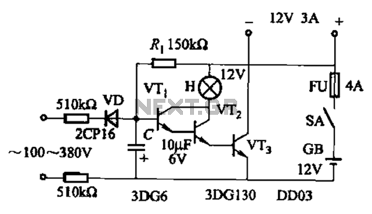
An AC-DC power supply without a power switching circuit is typically utilized for lighting load circuits. Once the power grid is restored, the standby power supply automatically switches on. An automatic switching circuit using a transistor is implemented, with...