
A typical DVD switching power supply circuit
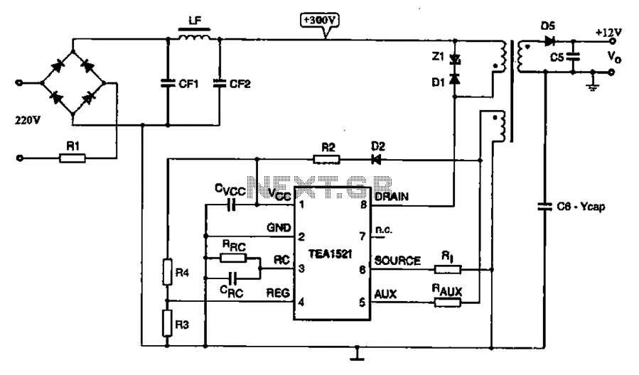
The DVD switching power supply circuit is an essential component in various digital devices, ensuring efficient power management during standby mode. The circuit employs a switching power supply architecture, which is characterized by its ability to convert electrical power efficiently by rapidly switching the input voltage on and off. The oscillation switch IC EA1623 plays a critical role in this process by generating oscillation pulses that drive the transformer.
In this design, the transformer acts as a key element, stepping down the voltage and isolating the output from the input. The secondary winding of the transformer produces an alternating current (AC) output, which is then rectified through a diode bridge to convert it into direct current (DC). Following the rectification process, a filter capacitor smooths out the output voltage, resulting in a stable +V voltage level suitable for powering the microprocessor control system.
The microprocessor control system circuitry relies on this stable voltage for its operation, allowing it to manage various functions within the digital product. Additionally, the circuit is designed to minimize energy consumption during standby mode, adhering to modern efficiency standards. Overall, this DVD switching power supply circuit exemplifies a well-structured approach to power management in electronic devices, combining performance, efficiency, and reliability.A typical DVD switching power supply circuit Is shown in digital products standby power supply circuit, which uses switching power supply structure, the oscillation switch IC T EA1623 provide oscillation pulse transformer for the switch. After switching transformer secondary output rectifier filter formed +V voltage for the microprocessor control system circuitry.
Related Circuits
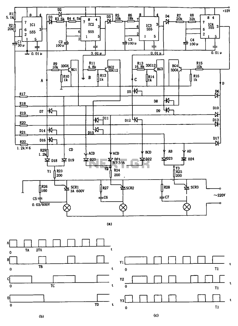
The decorative lamp control circuit is illustrated in the figure. The controller comprises a pulse generator, a frequency divider, a matrix circuit, and a thyristor control circuit. Components IC1, R1, R2, C1, and others form a multivibrator where the...

One of the most effective communication methods to be implemented in a digital system is the use of the RS232 serial line. The microcontroller 89S51 is equipped with a UART, allowing it to perform serial communication at RS232 levels...

This circuit design for an amplifier was created to address the gap in the 3-10 Watts power output range of audio amplifiers available in RED Free Circuit Designs. A straightforward, low-component-count amplifier was developed based on the successful 45...

This circuit is designed for differential analog circuit switches. The FM1208 monolithic dual differential multiplexer is utilized in applications where the RDS (ON) must be closely matched. The RDS (ON) for the monolithic dual multiplexer operates with a precision...
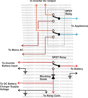
This inquiry has been presented multiple times on this blog regarding the implementation of a changeover selector switch for the automatic toggling of an inverter when AC mains power is available, and vice versa. The system must also enable...
The F232 device is powered via USB, but it requires a level translator at its output. The transmit (Tx) signal from the F232 must be converted to RS232 levels, as the receiving side has a maximum voltage requirement. The...