
3-Band Active Audio Tone Control Circuit
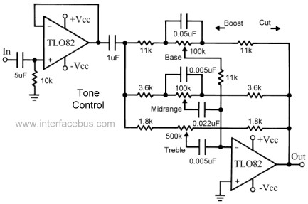
The 3-band active tone control circuit utilizes a combination of operational amplifiers and passive filter components to achieve precise audio frequency adjustments. The configuration allows for independent control over bass, midrange, and treble frequencies, facilitating a tailored audio experience. The circuit employs three distinct filter sections, each designed to target specific frequency ranges. The low-pass filter section is dedicated to bass frequencies, the band-pass filter section is designed for mid-range frequencies, and the high-pass filter section caters to treble frequencies.
In the design, each filter section incorporates an adjustable potentiometer that allows for real-time modifications to the frequency response. The selection of resistor and capacitor values for each filter is critical, as it determines the cutoff frequencies and the overall shape of the frequency response curve. The use of operational amplifiers, specifically the TL082, enhances the circuit's performance by providing high input impedance and low output impedance, which is essential for maintaining signal integrity.
The buffer amplifier at the input stage serves to isolate the tone control circuit from the source signal, ensuring that the tone adjustments do not load the input source. This is particularly important when connecting to various audio sources, as it minimizes the impact of the tone control circuit on the overall system performance. The design also allows for flexibility, as the buffer can be omitted if not needed, simplifying the circuit for applications where direct connection to the input source is feasible.
In summary, the 3-band active tone control circuit is a versatile solution for audio applications requiring precise frequency adjustments. It exemplifies the integration of active and passive components to achieve desired audio characteristics while maintaining signal quality and flexibility in design.This topic continues the coverage of audio tone controls. The first entry started with a Passive Tone Control circuit using different RC filter configurations and introduced an active filter. The second entry showed a fully designed 2-Band Active Tone Control circuit, and now this third section covers a 3-Band Active Tone Control circuit.
Compone nt values are sometimes provided as examples, but the final filter characteristics are left to the designer, although design equations are provided. Alternate configurations are possible for any of the circuit schematics, as these are all just low-pass or high-pass filters [active filters in the case of the Op Amps].
This audio tone control combines adjustments [RC filters] for a Base control a Midrange control and a treble control all in the same circuit. The design combines an operational amplifier, as the active element, with a passive filter section. The design also uses a buffer amplifier between the external input to the circuit and the actual tone control filters.
As indicated this circuit contains three individual filters, or one filter with three individual controls, that adjust the low band [Base], mid band [Mid-range] and high bands [Treble] of the audio range. As with the previous active tone control design the first part of the circuit is nothing more than a buffer and its presence does not effect the operation of the filter [tone control].
If the implementation does not require a buffer, than the first TL082 amplifier does not need to be used. That includes the 10k input bias resistor, and the 5uF blocking capacitor. The 1uF capacitor at the output of the Op Amp is also a DC block and is also not part of the filter circuit, but should be used as isolation between the filter and what ever input circuit is connected to it.
The configuration of the passive filter section differs from the previous examples. This circuit uses an individual adjustable resistor for each frequency band and a different resistor-capacitor pair per section. Notice how the [ high-pass ] treble circuit uses a series capacitor to the potentiometer, the [ low-pass ] bass circuit uses a capacitor in parallel with the potentiometer, and the [ band-pass ] mid-range circuit uses both a series and parallel capacitor.
Of course the values of the components are changing based on the 3dB point of the filters. The Op Amp used for this circuit example uses an TL082 Dual JET operational amplifier. Although that is just another example and many other amplifiers could be substituted for the Op Amp. The TL082 has an internally trimmed input offset voltage so does not require an Off-Set Voltage Adjustment. The TLO82 also does not include a frequency compensation pin, so no compensation capacitor is required.
However the amplifier still requires a 0. 01uF capacitor between each supply voltage pin and ground [not shown in the schematic for simplicity]. The TL082 is a dual package Op Amp, so there are two individual amplifiers per package [which share power lines].
Both amplifiers are used in the circuit above, or one if the buffer circuit is not required. The TL082 is available in either a 8-pin DIP Package [through-hole] or a 8-pin SOIC Package [surface mount]. 🔗 External reference
Related Circuits
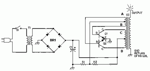
This circuit is designed to demonstrate high-frequency high voltage, capable of producing voltages up to approximately 30 kV, depending on the transformer used. It is economical and straightforward to construct, primarily utilizing a standard TV flyback transformer. The circuit...
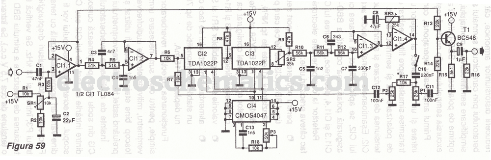
The first reverberator presented is based on the TDA1022, which is the most commonly used BBD (Bucket Brigade Device). Adjustments for proper functionality of the reverberator are required before connecting the power supply. The TDA1022 is a versatile BBD that...

This circuit amplifies sound signals from a condenser microphone to drive a small-sized loudspeaker. The key component is a pre-amplifier using a single transistor to increase the sound signal power before it is sent to an amplifier, specifically the...
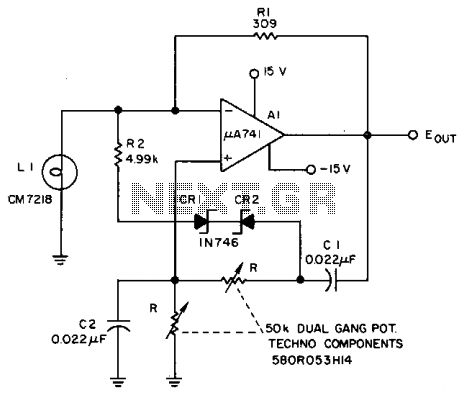
The Lamp LI stabilizes the loop gain at higher frequencies, while the limiting action of R2, CRI, and CR2 prevents clipping at low frequencies and increases the frequency adjustment range from approximately 3:1 to over 10:1. Additionally, waveform purity...
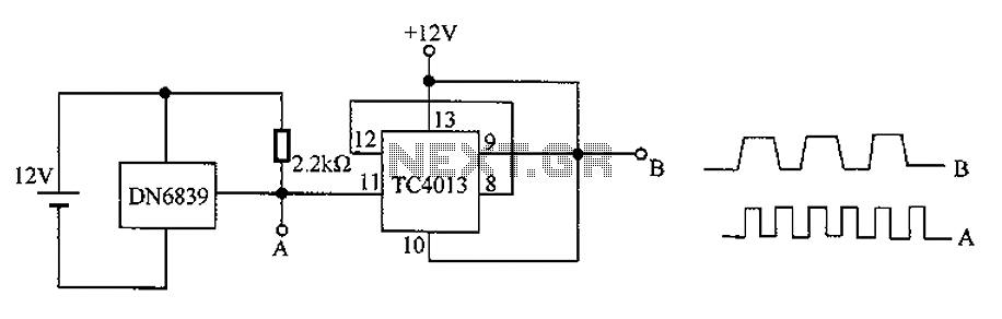
The circuit utilizes the integrated Hall element DN6839 for frequency division. It detects a magnetic field through the pulsating DN6839, generating a pulse waveform. The circuit is designed for applications involving very high-frequency pulsating magnetic fields. It employs the...
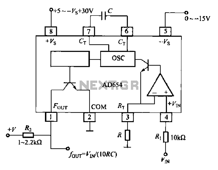
The AD654 voltage-frequency converter is a low-cost device that operates with a single supply voltage ranging from +5V to +36V, as well as with dual supplies of +5V to +18V. It can handle a maximum input voltage of 36V...