
Solid State Tesla Coil/High Voltage Generator Circuit
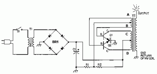
The circuit utilizes a high-voltage flyback transformer (T2), which is the core component responsible for generating high voltages. The flyback transformer operates on the principle of electromagnetic induction, where the primary winding is energized to create a magnetic field that induces a high voltage in the secondary winding. The rewinding of the primary and secondary windings is crucial for ensuring the correct voltage output and the safe operation of the circuit. The choice of wire gauge is important; 18 AWG is used for the primary to handle the necessary current, while 22 AWG is used for the secondary to ensure a compact winding and adequate voltage output.
Transistors Q1 and Q2 are typically configured in a push-pull arrangement to drive the transformer efficiently. The use of heatsinks is imperative to dissipate heat generated during operation, preventing thermal runaway and potential failure of the transistors. Resistors R1 and R2 serve to limit the current through the transistors, thus protecting them from excessive current and ensuring stable operation.
Safety measures are paramount when working with high-voltage circuits. Proper insulation, the use of non-conductive materials, and maintaining a safe distance from grounded objects are essential practices. Additionally, the circuit should be housed in an enclosure to prevent accidental contact with high-voltage components.
In conclusion, this high-voltage generator circuit is a practical demonstration of high-frequency high-voltage principles, offering a variety of applications while emphasizing the importance of safety and proper construction techniques.This is a fun and useful circuit for demonstrating high frequency high voltge. It can produce up to about 30KV, depending on the transformer used. It is cheap and easy to make, thanks to the standard TV flyback transformer used. It can power LASERS (although I have never tried), demonstrate St. Elmo`s fire, and even cause a fluorescent bulb to ligh t from as much as 2 feet away. 1. T2 is a high voltage flyback transformer salvaged from an old TV, or ordered from Fair Radio Sales (see Where To Get Parts). Look for the biggest, most intimidating transformer you can find. Old tube TV`s are a good place to look. The transformer should not have a rectifier built in. 2. You will need to rewind the transformer`s primary. First, remove the old primary, being careful not to damage the high voltage secondary. If the transformer is wound with all windings incased in plastic, use another transformer. Second, wind on 5 turns of 18 AWG wire, twist a loop (center tap), and then wind on 5 more turns. This becomes winding C-D. Now, wind on 2 turns of 22 AWG wire, twist a loop, and wind on 2 more turns. This becomes winding A-B. 3. Q1 and Q2 will run HOT if not used with a large heatsink. After the circuit has been running for a minute or two, you should still be able to put your finger on the transistors without being burnt.
Also, R1 and R2 will run hot. 4. If you experience arcing on the exposed transformer leads, select a lower voltage for T1. If you are powering the circuit with a power supply (see Power Supply), just crank down the voltage. The first picture is the high voltage generator without the voltage multiplier. Notice how hot the arc looks. The second picture is the high voltage generator with a voltage multiplier installed. Notice how much brighter the arc is. The above pictures of myself were taken with me standing on an pie plate that was resting on the top of a plastic bucket. The pie plate was connected to the high voltage generator and charged to about 40, 000V. If you do this, be sure to have someone else turn on and off the high voltage generator. Also, don`t touch anything when you are charged. Have everything you are going to hold/play with already sitting on the bucket and away from grounded objects.
Remember to take off your watch. 🔗 External reference
Related Circuits
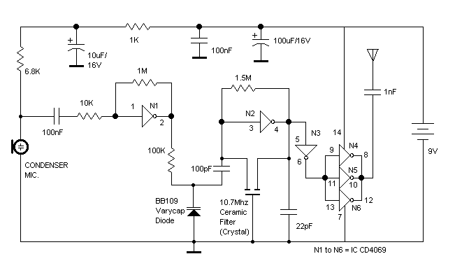
The RF oscillator using the inverter N2 and 10.7MHz ceramic filter is driving the parallel combination of N4 to N6 through N3. Since these inverters are in parallel, the output impedance will be low so that it can directly...
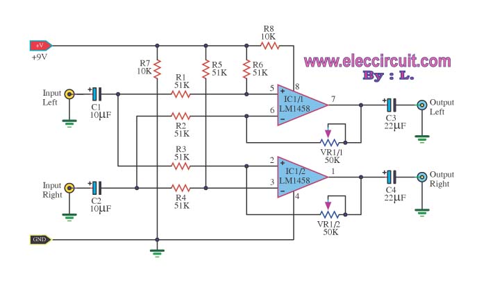
The LM1458 integrated circuit (IC) is utilized to amplify the difference in the left input signal (L), resulting in a surround sound effect. The left signal is coupled through capacitor C2 and resistor R1 to pin 5 of IC1...
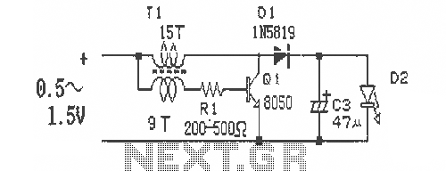
This is a simple and easy-to-build DC-DC driver circuit designed for a single flashlight battery, operating at a parametric voltage of 1.5V. The input current is 90mA, while the light-emitting diode (LED) current is 26mA or higher. The circuit...
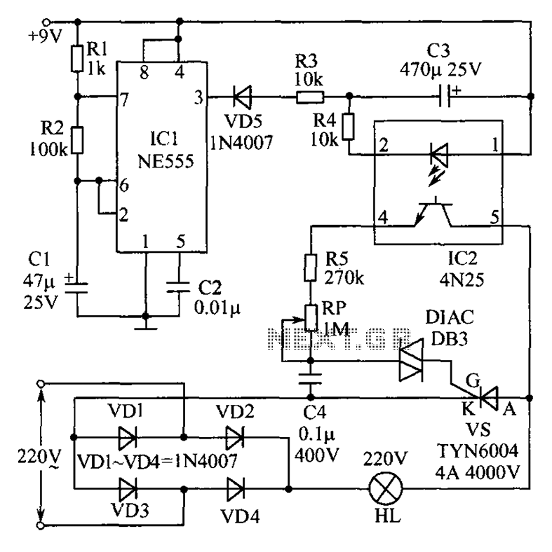
This circuit features an appealing Christmas lights setup. Upon activation, the lights (HL) gradually increase in brightness. Once they reach maximum brightness, they automatically dim, and upon reaching the lowest brightness, they gradually brighten again, creating a smooth transition...
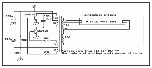
The telephone ring generator illustrated below produces the necessary high voltage using a simple switching mode power supply (SMPS) that incorporates a CMOS Schmitt Trigger square wave oscillator, a 10 mH inductor, a high voltage switching transistor (such as...
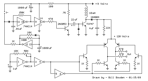
Here is the schematic diagram for a 20 Watt driver. I developed this circuit in 1985, and used it to build a lamp that found much use both as camping light and as emergency light during the then-frequent power...
Warning: include(partials/cookie-banner.php): Failed to open stream: Permission denied in /var/www/html/nextgr/view-circuit.php on line 713
Warning: include(): Failed opening 'partials/cookie-banner.php' for inclusion (include_path='.:/usr/share/php') in /var/www/html/nextgr/view-circuit.php on line 713