
Voltage - frequency conversion circuit
The AD654 voltage-frequency converter is designed to convert a varying voltage input into a corresponding frequency output, making it suitable for various applications in analog signal processing. The device operates effectively within the specified voltage ranges, allowing for flexible integration into different circuit designs. The maximum input voltage of 36V ensures compatibility with a wide range of systems, while the operating frequency capability of 500kHz allows for high-speed applications.
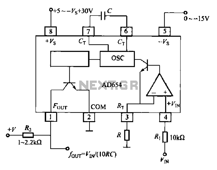
In the voltage-frequency conversion circuit, the input voltage is fed into the voltage-controlled oscillator (VCO), which generates an output frequency that is directly proportional to the input voltage. The relationship between the input voltage and the output frequency is defined by the equation f_out = V_in / (10RC), where R and C are external components that set the time constant of the circuit. This relationship indicates that by adjusting the values of R and C, the designer can tailor the frequency response of the circuit to meet specific requirements.
The static current of 2.0 mA signifies low power consumption, making the AD654 suitable for battery-operated devices or energy-sensitive applications. Additionally, the typical temperature coefficient of 50 x 10^-6 °C suggests that the device maintains stable performance over a range of operating temperatures, while the drift of 4 mV/°C indicates minimal variation in output voltage with temperature changes.
For practical implementation, the O pin output configuration requires a pull-up resistor to ensure proper operation when the collector electrode is open-circuit. This design consideration is crucial for achieving reliable signal output. The four-way output frequency capability allows for multiple signal outputs from a single input voltage, enhancing the versatility of the AD654 in various electronic applications. Overall, the AD654 voltage-frequency converter is a robust solution for converting voltage signals into frequency outputs in a cost-effective manner.AD654 voltage-frequency converter is a low cost, they can work at + 5 ~ + 36V single supply, can also work in 5 18V dual supplies a maximum input voltage of 36V, the maximum op erating frequency of 500kHz, static current is 2. OmA, typical temperature coefficient of 50 10 -6lcc, typical drift 4vV/C. Voltage-frequency converting circuit as shown 10--40 shows the basic voltage-frequency conversion circuit. pin voltage from the input voltage controlled evacuation amplified voltage controlled oscillator frequency of the oscillator is changed, the signal by the driver circuit from O pin output (for the collector electrode open-circuit output, you need to access the pull-up resistor).
Electric four-way output frequency by the input voltage vl, and external connection R, C decided fuu-r yIN/(10RC)
Related Circuits
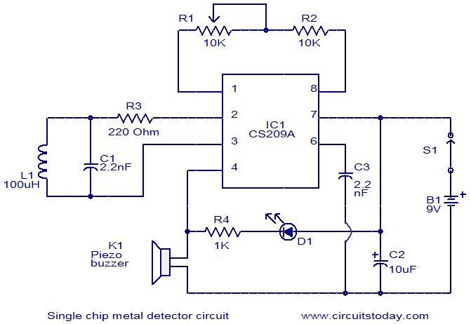
This is a simple single-chip metal detector circuit based on the IC CS209A from Cherry Semiconductors. A 100µH coil is utilized to detect the presence of metal. The IC CS209A incorporates a built-in oscillator circuit, with the coil (L1)...
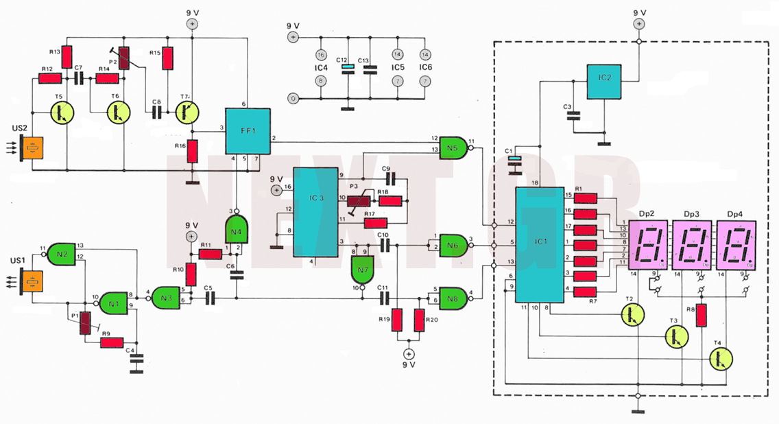
The circuit utilizes ultrasonic oscillations to measure the distance between two points based on the speed of sound in air. By measuring the time it takes for the ultrasonic wave to travel between these points, the distance can be...
Frequency Shift Keying (FSK) refers to the method of transmitting digital data over a signal path, which can include two wires, telephone lines, or AM/FM transmitters. Typically, two signals are transmitted: one corresponding to a logical '1' and the...
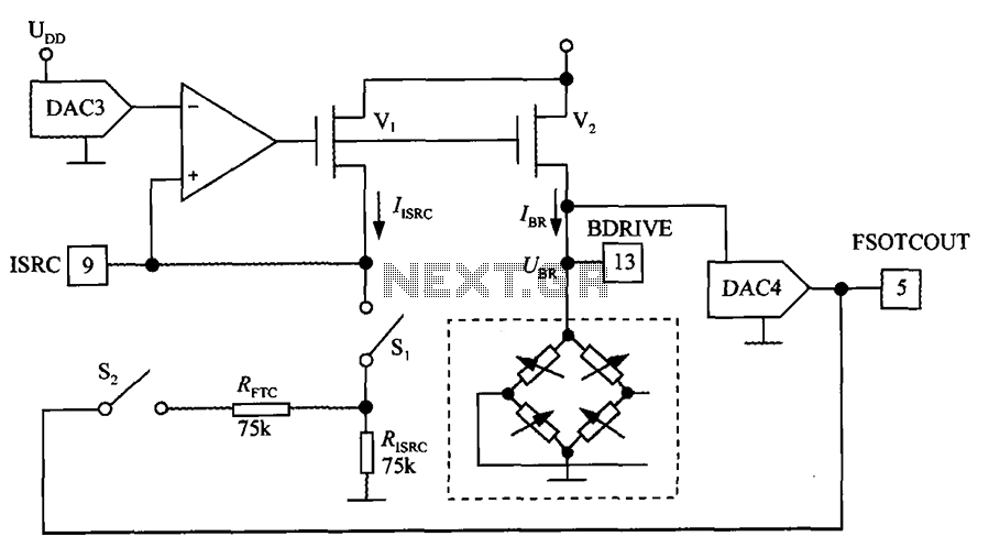
The excitation circuit for the digital pressure signal conditioner MAX1458 is illustrated. The output DAC3 is utilized to adjust the sensor excitation current (IBR), enabling full-scale fine calibration. The reference current (IISRC) is determined by the resistor RISRC and...
The circuit is a battery charging system powered by Q2, Q6, R8, and D10, which provides constant current to charge the battery. When an external power supply is present, the charging current flows through R8 and D10 to charge...
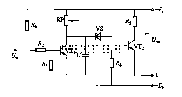
The circuit is a rechargeable short delay control for a conducting pipe, featuring two adjustment potentiometers (RP) that enable the delay time to be set from several hundred milliseconds to several seconds. The rechargeable short delay circuit is designed for...