
3 Band Equalizer Circuit

The three-band equalizer circuit employs an operational amplifier to achieve tone control across different frequency bands. The circuit typically consists of three separate filters, each designed to adjust the gain of a specific frequency range: low frequencies for bass, mid frequencies for midrange, and high frequencies for treble.
The implementation begins with the op-amp configured in a non-inverting amplifier setup, where the input audio signal is fed into the non-inverting terminal. Each band consists of a passive filter network that can be adjusted using potentiometers, allowing the user to boost or cut the desired frequency bands.
For the bass control, a low-pass filter is utilized, which allows frequencies below a certain cutoff to pass through while attenuating higher frequencies. Similarly, the midrange control is achieved using a band-pass filter that selectively amplifies mid frequencies while rejecting both lower and higher frequencies. The treble control employs a high-pass filter, allowing frequencies above a specific cutoff to pass through while attenuating lower frequencies.
The output of each filter is then summed together at the output of the op-amp, resulting in an audio signal that has been modified according to the settings of the three potentiometers. This circuit is widely used in audio applications for adjusting sound quality and tailoring the audio output to suit personal preferences or specific acoustic environments.
Careful component selection, including the values of resistors and capacitors in the filter networks, is crucial to achieving the desired frequency response. Additionally, power supply decoupling may be implemented to ensure stable operation of the op-amp, preventing noise and distortion in the audio signal. Overall, this three-band equalizer circuit provides a versatile and effective means of controlling audio frequency response in various applications.Here is 3 band equalizer circuit other. A tone control circuit made with a single op-amp and having three ranges, bass, middle and treble controls. Using a. 🔗 External reference
Related Circuits
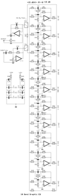
This circuit employs a single integrated circuit, TL074, to create a 5-band graphic equalizer suitable for high-fidelity audio systems. The equalizer is compatible with radio-cassette players and car stereos. It boasts low distortion and noise levels, a wide operating...
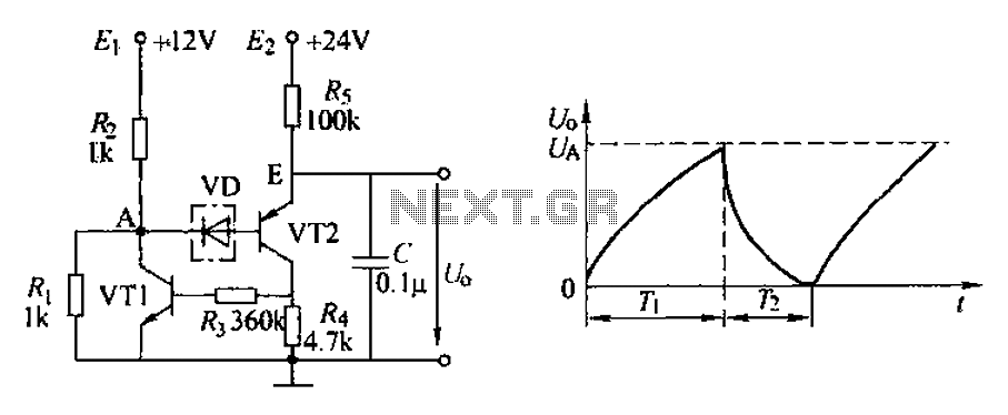
The application circuit depicted is a complementary sawtooth generator. In the schematic, VT1 is the transistor with a base current limiting resistor, which prevents excessive base current flow through the crystal tube. The resistor R4 acts as a bleeder...
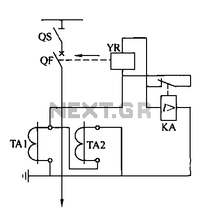
Operating power protection devices can be categorized into two types: DC power supply operation and AC operation. AC operating power is favored due to its lower investment costs, simpler operation, and reliable secondary circuit maintenance, making it widely used...
Project Manager Jim Heck, G3WGM, has provided an exclusive audio interview to Bob McCreadie, G0FGX, from TX Factor, detailing the tests and potential issues involved. Membership in AMSAT-UK is available to anyone interested in amateur radio satellites or space...

This is a simple circuit design for a two-station intercom system utilizing common 8-ohm mini speakers. The press-to-talk switches should feature a spring-return mechanism to ensure that the intercom cannot be left in the ON position. The circuit requires...
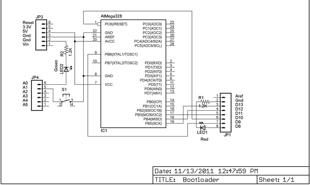
This Lazy Old Geek is also an Arduino enthusiast. One of the common microcontrollers used by Arduinos is the Atmega328 chip. To utilize Arduino software, the Atmega must be equipped with bootloader software. There is a notable difference between...