
Relay protection circuit

The direct-action protection circuit employs a manually operated mechanism within the overcurrent release (trip coil) YR, functioning as a direct-acting overcurrent relay. This relay is connected in a two-phase configuration or as a two-relay device type. During normal operation, the current through YR is significantly lower than the operating current, resulting in no action. In the event of a second-phase short circuit, YR activates to trip the circuit breaker QF. This operational mode is economically simple but offers low sensitivity and is rarely utilized.
In contrast, the shunt trip protection circuit operates differently. During normal operation, the current relay KA's normally closed contact shorts the trip coil YR. Consequently, YR does not trip the circuit breaker QF. When a phase short circuit occurs in the primary circuit, the current relay KA activates, opening the normally closed contacts and disconnecting the short-circuit trip coil YR from the current. This process, referred to as "de-streaming," allows the secondary current from the current transformer to flow entirely through YR, which then trips the circuit breaker QF, a process known as "de-shunt trip." This wiring method is relatively straightforward, reliable, and sensitive, although it requires that the breaking contacts of the current relay KA have sufficient capacity. Current relays such as GL15, GL16, and GL25, GL26 available on the market have large capacity contacts, capable of handling short break currents up to 150A, thus meeting the requirements for the shunt trip operation. As a result, this operational mode is widely implemented in power supply systems within factories.
The schematic design of these protection circuits involves integrating the trip coil YR with the circuit breaker QF and the current relay KA. The direct-action circuit requires a simple connection where the relay YR is directly linked to the overcurrent release mechanism, allowing for manual reset after tripping. In the shunt trip circuit, the current relay KA must be positioned to ensure it can effectively disconnect the trip coil YR when a fault occurs. The connection between the current transformer and YR must be designed to handle the expected load currents, ensuring that the sensitivity of the protection mechanism is adequate to detect faults without nuisance tripping.
In summary, the design considerations for these protection circuits focus on ensuring reliability, sensitivity, and the ability to handle fault conditions while maintaining ease of operation and cost-effectiveness, particularly in small factory environments. The choice between direct-action and shunt trip methods is influenced by the specific requirements of the application, including sensitivity to faults and the operational characteristics of the electrical system.Operating power protection devices, there is a DC power supply operating power and AC operation into two categories. Since the AC operating power with less investment, operation and maintenance is simple and convenient and reliable secondary circuit, so it is widely used in small factories. (1) Direct-action protection circuit uses off circuit breaker manually operated mechanism within the overcurrent release (trip coil) YR as a direct-acting overcurrent relay , a relay connected into a two-phase or two-phase two-relay device type.
During normal operation, the current YR by far less than the operating current, and therefore no action. In a second phase short circuit when the circuit, YR movements to trip the circuit breaker QF, this mode of operation is simple by economic, but the protection of low sensitivity, in fact seldom used, as shown in FIG.
(2) to shunt trip protection circuit shown in Figure b. Normal operation, the current relay KA normally closed contact will short-circuit trip coil YR stream. YR no current through the circuit breaker QF is not so trips. When the primary circuit phase short circuit, the current relay KA action, the normally closed contacts disconnect, short-circuit trip coil YR partial stream branch is removed, the so-called "de-streaming", so that the current transformer secondary current all through YR, QF causing the circuit breaker tripped, the so-called "de-shunt trip." Wiring this mode of operation is relatively simple, reliable and sensitive, but requires current relay KA breaking contacts can force big enough.
GL15,16 on the market and other types of GL25,26 current relay, which contacts a large capacity, short break current unitary division of 150A, fully able to meet short circuit "to shunt trip" requirements. Therefore, this mode of operation to shunt trip power supply system in the factory now applied quite widely.
Related Circuits
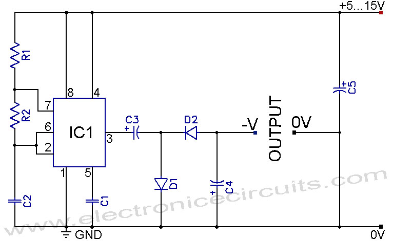
A 555 negative voltage power supply circuit can be created using a charge-pump configuration that incorporates a 555 timer, diodes, and additional components. The 555 timer is a versatile integrated circuit commonly used in various applications, including oscillators, timers, and...

All of ACC's repeater and remote base products support the control of synthesized remote base transceivers. One form of frequency control supported is compatible with transceivers using thumbwheel frequency selection. The controllers supply BCD (binary coded decimal) formatted data...
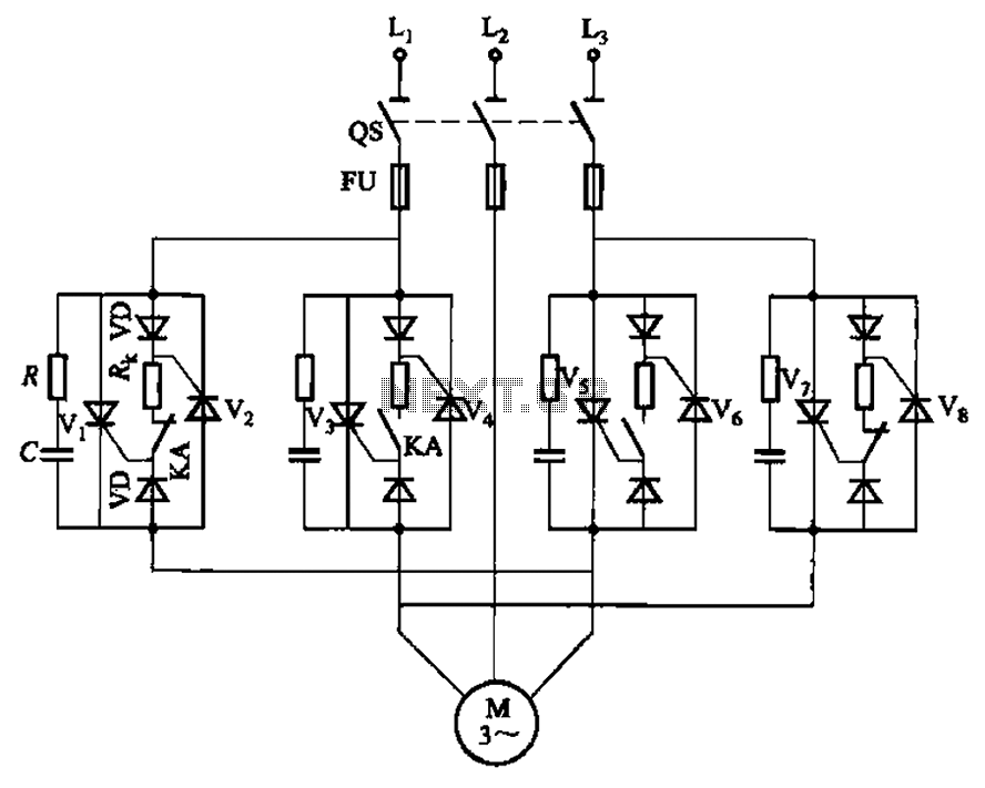
The circuit depicted in Figure 3-69 is designed for applications requiring frequent timing control for motor reversing operations. In this configuration, thyristors V1, V2, V7, and V5 are utilized for positive control of rotation, while thyristors V3, V4, and...
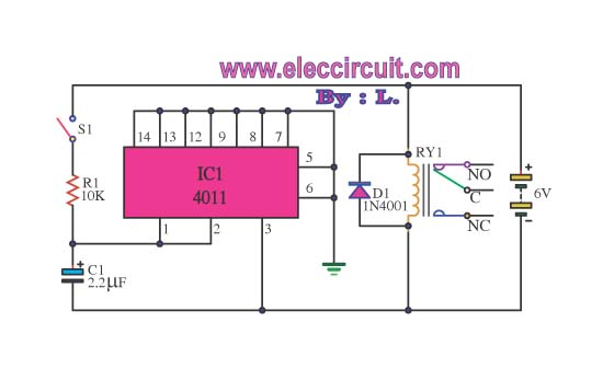
This circuit illustrates the use of the 4011 integrated circuit (IC) for a surge protection electronic circuit diagram. Features include the ability to delay the activation of other appliances connected to the output. The 4011 IC is a quad 2-input...
This circuit is beneficial for applications where a load must be activated from one location and deactivated from another. Multiple momentary normally open (N/O) switches or push buttons can be connected in parallel. The circuit described facilitates remote control of...

Daylight shutoff; the schematic has been updated but is not shown here. The daylight shutoff circuit is designed to automatically turn off lighting systems during daylight hours, thereby conserving energy and extending the lifespan of the lighting fixtures. Typically, this...