
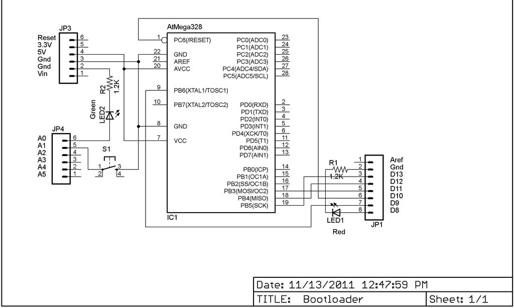
My Arduino In Circuit Programmer
The signature refers to a specific code hardwired into the chip for identification purposes. Most bootloader software appears to be designed for the 0x950F signature, while the chip in question may have a different signature. This code is similar to ROM code that cannot be altered. Hexadecimal numbers, which start with 0x, represent values from 0 to 15 instead of the decimal system's 0 to 10. The bootloader software encountered was based on the 0x950F signature, which corresponds to the Atmega328P-PU chip. In the field of electronics, it is common to overlook letters following the number, as they typically denote revisions. However, in this instance, the revision also impacts the bootloading process.
A successful setup was achieved on a breadboard with some software modifications, but a more permanent solution was desired. A protoshield similar to that used in the AdaFruit write-up was available, but it was reserved for future projects, leading to the decision to construct a custom shield. Standard prototype PCBs typically have solder pads on only one side, and in this case, the pads were placed on the bottom to accommodate the IC socket. However, this design posed a challenge for soldering header pins to connect to the Arduino, as they were positioned on the bottom.
Standard prototype PCBs have a 0.1-inch spacing between holes, which is conventional for most electronic components. Many Arduino users are aware that original Arduinos had three connectors aligned correctly on 1/10-inch centers, but the fourth connector was slightly offset, complicating the creation of Arduino shields on standard prototype PCBs. Solutions proposed by hobbyists often involve bending header pins to fit. In this case, the header pins were too short to bend, prompting a different approach. For the offset connector, the location was marked on the protoboard, and a Dremel tool was used to create a slot for the connector.
To facilitate alignment and simplify the hot-gluing process, an Arduino clone was used. Due to a tendency to create a mess while hot gluing, a male header strip was partially inserted into the female headers. A strip of transparent tape was pinched between the male and female headers to prevent glue from adhering to the female headers. After the glue cooled, the headers could be carefully removed, possibly using a knife or small screwdriver, aided by the tape.
The detailed description of this circuit design emphasizes the challenges faced in programming the Atmega328 chip with the correct bootloader and the innovative solutions developed to create a custom Arduino shield. Key aspects include the identification of device signatures, the importance of proper spacing for connectors, and the practical techniques employed to ensure a clean and effective assembly process.This Lazy Old Geek is also an Arduino Geek. If you are an Arduino Geek, one of the common microcontrollers used by Arduinos is the Atmega328 chip. In order to use Arduino software, the Atmega must have bootloader software on it. I didn`t realize there was a difference. As far as I can tell, the Atmega328P-PU has lower power but it also has a diffe rent device signature which is important to Arduino users. As of November 2011, the Atmega328-PU is cheaper by about $1. Problem: So there are hundreds of articles on installing bootloader on the Atmega328. I built one using another Arduino to program the chip. I built one using the USB-BUB to program the chip. I built one using a parallel port to program the chip. Well, even after a week of troubleshooting and searching the Internet, none of them worked. So I gave up. I am usually a very persistent hacker but I`m getting old so I gave up. Well, this one looked a lot like most of the others I`d built. But it was from AdaFruit which has some of the best tutorials (accurate, complete, well documented) I`ve seen for the Arduino and it had different code. So I hacked up the hardware (See picture) using a RBBB Arduino and loaded the software. And guess what. It still didn`t work. Signature: So what is a signature Well, it turns out it is a specific code hard wired into the chip to identify it.
Now all of the bootloader software seemed to be looking for 0x950F and not 9514 or 0G—9514. GeekSpeak: This is like ROM code that cannot be changed. By the way when you see programming code written starting with 0x` that means it is a hexadecimal number. I won`t go into details but hexadecimal numbers go from 0 to 15 instead of 0 to 10. Signature: So it turns out the bootloader software I`ve seen were based on the 0x950F signature which is the signature for the Atmega328P-PU chip.
Being in electronics for 40 years, I usually ignored letters after the number. They are usually just revisions. This is basically true but in this case, the change also affects bootloading. Solution: Well, I did get it to work with my breadboard setup with some software changes discussed later but I wanted a more permanent setup. I did have a protoshield like the one used in the AdaFruit writeup but I wanted to save mine for future projects so I decided to build my own shield.
Problem: These PCBs have solder pads on only one side. I decided to put the pads on the bottom so the IC socket could be soldered in. The problem is the header pins going into Arduino go on the bottom couldn`t be easily soldered. Problem: The standard prototype PCBs have 0. 1 spacing between holes. This is standard for most electronics components. As many Arduino Geeks know, the original Arduinos had three connectors spaced correctly on 1/10 centers but the fourth connector was offset slightly. What this means is that Arduino shields cannot be easily made on standard prototype PCBs. Solution: Hobbyists/Instructablers have come up with solutions for this. Most involve bending header pins to fit. Well, my header pins are a little short to bend so I decided to go a different route. For the one connector that was offset, I marked the location on the protoboard. Then I used a Dremel-clone to cut a slot there for the connector. I wonder if a laser engraver could cut this slot. Hot-glue procedure: I wanted to use an Arduino (clone) to get the pins lined up and make the gluing easier.
But I`m a messy hot gluer so I took some male header strip and inserted it part way into the female headers. (See picture) Then I took a strip of transparent tape and pinched it in between the male and female header.
(See picture). It`s hard to see the tape but the reflections are an indicator. After it cools, you can carefully pull the headers out maybe with a knife or small screwdriver. The tape helps keep the glue from sticking to the female headers. Now it can be removed. 🔗 External reference
Related Circuits
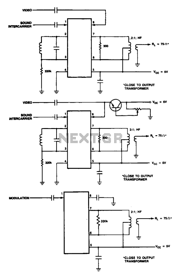
These are modulator circuits designed for the modulation of video signals on a VHF/UHF carrier. The circuits require a 5 V power supply and a few external components for negative modulation mode. For positive modulation, an external clamp circuit...
Mobile phone chargers available in the market are quite expensive. The circuit presented here serves as a low-cost alternative to charge mobile telephones or battery packs with a rating of 7.2 volts. The proposed circuit design utilizes a straightforward approach to...
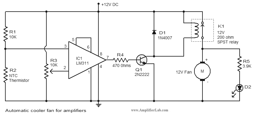
An automatic cooler fan for amplifiers is a circuit designed to conserve power in amplifier circuits. This circuit activates the fan. The automatic cooler fan circuit for amplifiers operates by utilizing temperature sensors to monitor the heat generated by the...
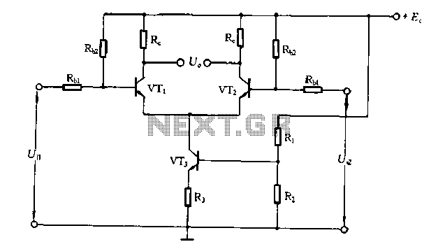
The differential amplifier circuit features a constant current source. The differential amplifier is a fundamental building block in analog electronics, utilized for amplifying the difference between two input voltages while rejecting any signals that are common to both inputs. Central...
This device is a simple timer that keeps the headlights of a vehicle on for approximately 1 minute and 30 seconds, allowing for illumination when accessing dark areas without the need to return to switch off the lights. Pressing...
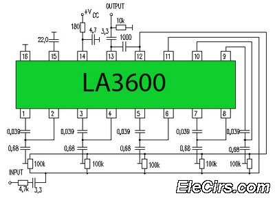
Circuit LA3600 5 Band Equalizer Circuit Schematics. One type of tone control in audio electronics is the graphic equalizer. Graphic equalizers can be categorized into two types: bar and other configurations. The LA3600 circuit is a 5-band graphic equalizer designed...