
3 Band Graphic Equalizer
The circuit employs a single op-amp configured in a non-inverting amplifier configuration, allowing for both gain and attenuation adjustments. The frequency response is shaped by passive components, including resistors and capacitors, which define the cutoff frequencies for each band. The low-frequency range is centered around 50 Hz, the mid-frequency range is centered around 1 kHz, and the high-frequency range is centered around 10 kHz.
The design incorporates a potentiometer for each frequency band, enabling users to adjust the gain or cut smoothly. This allows for fine-tuning of the audio signal based on personal preference or specific audio requirements. The op-amp's feedback network is configured to achieve the desired gain levels while maintaining stability and minimizing distortion.
Power supply considerations are crucial in this design. The op-amp can operate within a wide voltage range, making it versatile for various applications. However, to achieve the full ±20 dB boost, an 18-volt supply is necessary. Lower supply voltages will reduce the maximum achievable gain, which should be taken into account during circuit implementation.
In summary, this equalizer circuit is an effective solution for audio signal processing, providing adjustable gain across three distinct frequency ranges while being simple to construct and adaptable to different power supply conditions.Using a single op-amp this easy to make equalizer offers three ranges, low frequency, mid frequency, and high. With component values shown there is approximately +/-20dB of boost or cut at frequencies of 50Hz, 1kHz and 10kHz.
Supply voltage may be anything from 6 to 30 Volts. Maximum boost 20dB is only realized with maximum supply voltage of 18 Volt . 🔗 External reference
Related Circuits
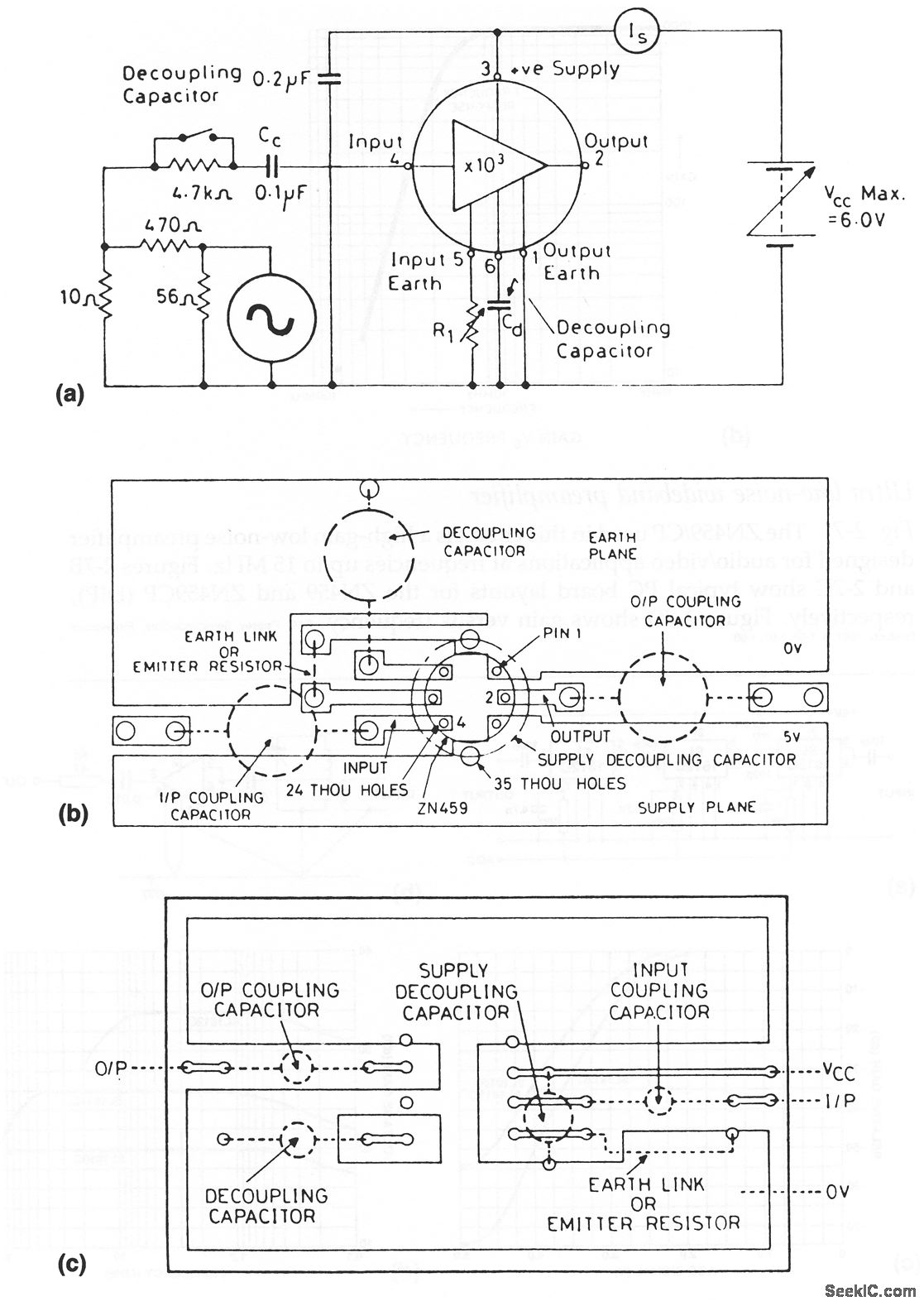
The ZN459/CP utilized in this circuit is a high-gain, low-noise preamplifier intended for audio and video applications at frequencies reaching up to 15 MHz. Figures 2-7B and 2-7C illustrate typical printed circuit board layouts for the ZN459 and ZN459CP...
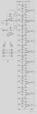
The diagram illustrates a circuit comprising 10 identical units, each varying only in the capacitance values of their capacitors, which determine the frequency band for each filter. Potentiometers are utilized to adjust the designated frequency regions in each unit....
A bandpass filter passes a range of frequencies while rejecting frequencies outside the upper and lower limits of the passband. The range of frequencies to be passed is called the passband and extends from a point below the center...
The circuit was designed to operate a frequency modulation voice transmitter over the FM band within the VHF frequency range. The transmitter is an electronic device. The frequency modulation (FM) voice transmitter circuit operates within the VHF (Very High Frequency)...

A unified thermometric controller that can be programmed with simple scripts, integrating the "classic" thermometer/controller pair. You can build a variety of simple machines with the same hardware and a different script: a charting thermometer, a vending machine that...
The circuit design aims to create a preamplifier for television systems that operates within the UHF frequency range of 450 MHz to 800 MHz. The preamplifier circuit is essential for enhancing weak television signals before they are processed by the...