
3 Band Graphic Equalizer Circuit
The graphic equalizer circuit operates by dividing the audio frequency spectrum into multiple bands, typically centered around specific frequencies. In this case, the circuit utilizes three distinct frequency bands, which allows for the adjustment of the amplitude of audio signals within those bands.
The design may incorporate either passive components, such as resistors, capacitors, and inductors, or active components, including operational amplifiers, depending on the desired performance and application. In a passive equalizer, the frequency response is shaped through the use of passive filters, which do not amplify the signal but rather attenuate certain frequencies. Conversely, an active equalizer employs amplifiers to provide gain, allowing for greater control over the output signal and the ability to boost specific frequency ranges.
The circuit typically includes a set of sliders or knobs that allow the user to adjust the gain for each frequency band. These adjustments modify the audio signal's frequency response, enhancing or diminishing specific frequencies to achieve the desired sound profile. The output of the equalizer can then be fed into an audio amplifier or directly to speakers.
In addition to the basic components, careful consideration is required for the selection of the center frequencies and the bandwidth of each band, as these factors significantly influence the overall performance of the equalizer. The design may also include additional features such as bypass switches, which allow the user to compare the equalized signal with the original audio signal, and LED indicators to provide visual feedback on the settings being used.
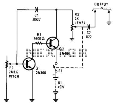
Overall, the graphic equalizer circuit serves as a powerful tool for audio processing, enabling users to tailor acoustic signals to their preferences or to compensate for deficiencies in the sound system or listening environment.The circuit illustrates the use of 3 frequencies to produce a graphic equalizer that will be used for acoustic signals. Equalizer a passive or an active.. 🔗 External reference
Related Circuits
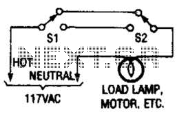
This switching arrangement is utilized in both domestic and industrial environments to enable control of a light or other AC-operated device from multiple locations. This switching arrangement, commonly referred to as a multi-way switching system, is designed to facilitate the...
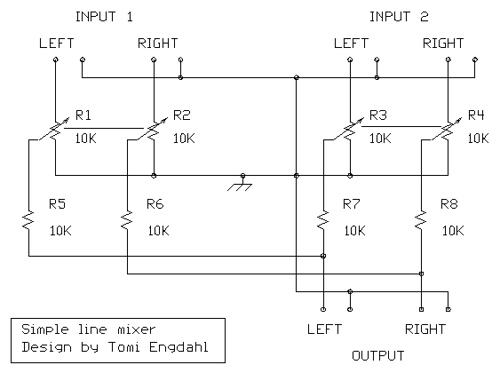
The mixer circuit described features three line inputs and three microphone inputs. The microphone inputs are designed for low impedance dynamic microphones with a range of 200 to 1000 ohms. Alternatively, an electret condenser microphone (ECM) can be used,...
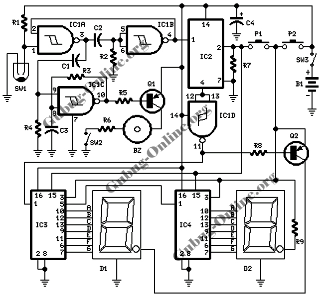
This design features a signal logic tester that utilizes a common cathode seven-segment display. The display indicates a logic level "1" (represented by an "H" on the display) or a logic level "0" (represented by an "L" on the...
The purpose of this circuit is to power a lamp or other appliance for a specified duration (30 minutes in this case) and then automatically turn it off. This feature is particularly useful for reading in bed at night,...
Useful for troubleshooting audio, video, and lower frequency RF amplifiers. This circuit generates a signal that is rich in harmonics. The circuit designed for troubleshooting audio, video, and lower frequency RF amplifiers is crucial for diagnosing issues in these systems....
This circuit is a conventional Pierce type oscillator that utilizes a JFET. It employs fundamental mode crystals and demonstrates good performance and reliability when a low noise JFET is used. The feedback is regulated by the capacitance C1, which...