
Signal Generator Circuit

The circuit designed for troubleshooting audio, video, and lower frequency RF amplifiers is crucial for diagnosing issues in these systems. It generates a signal characterized by a rich harmonic content, which is essential for testing the frequency response and linearity of amplifiers. The harmonic-rich signal can effectively reveal distortion, frequency response anomalies, and other performance-related issues within the amplifier circuits.
The circuit typically consists of a signal generator that produces a fundamental frequency, followed by a series of nonlinear components that introduce harmonics. These nonlinear components can include diodes, transistors, or specialized harmonic generation ICs. The output of the circuit may be connected to an oscilloscope or a spectrum analyzer to visualize the harmonic content and assess the amplifier's performance.
In audio applications, the generated signal can simulate complex waveforms, allowing for thorough testing of audio amplifiers. For video systems, the harmonic content can help in identifying issues related to bandwidth and signal integrity. In lower frequency RF applications, the circuit can assist in evaluating the linearity and gain of RF amplifiers, ensuring they operate within specified parameters.
In summary, this circuit serves as a vital tool for engineers and technicians in the field of electronics, providing a means to troubleshoot and optimize amplifier performance across various applications. Its ability to generate a harmonic-rich signal makes it an invaluable asset in the testing and maintenance of audio, video, and RF amplification systems. Useful for troubleshooting audio, video, and lower frequency RF amplifiers, this circuit generates a signal that is rich in harmonics. 🔗 External reference
Related Circuits
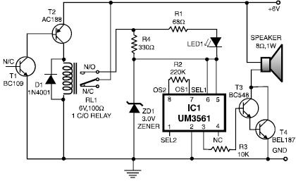
This heat detector alarm electronic project is designed using the UM3561 sound generator circuit and several common electronic components. The heat detector circuit employs a complementary pair of npn and pnp transistors to sense heat. When the temperature near...

The gain of the single-stage virtual earth amplifier IC1 is determined by the drain-source resistance of the field-effect transistor (FET). Resistors R1, R2, and R3 linearize the FET's voltage-current characteristic. A control voltage is derived from the output signal...
The circuit described here is that of a metal detector. The operation of the circuit is based on the superheterodyning principle, which is commonly used in superhet receivers. The circuit utilizes two RF oscillators. The frequencies of both oscillators...

The infrared transmitter circuit, as depicted in Figure 18-la, utilizes transistors VT1 and VT2 along with RC components to create an astable multivibrator. The circuit operates with VT1 and VT2 receiving base bias from resistors, and closing switch SA...

The application involves observing the light pulse emerging from a thick specimen after transillumination by a laser pulse. Pulses derived from the laser source are amplified using a Video Amplifier LM733. The reference level is set to 1 V...
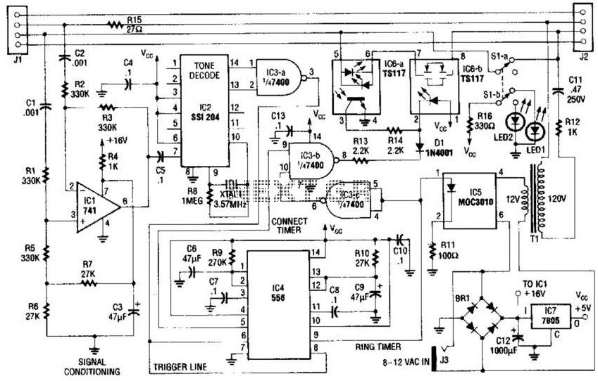
The fax mate separates the fax machine from the phone line, rings the fax machine on command, connects equipment to incoming lines, and senses the end of the message. When a touch tone pound signal (#) is detected, it...