
Simple Battery Level Indicator
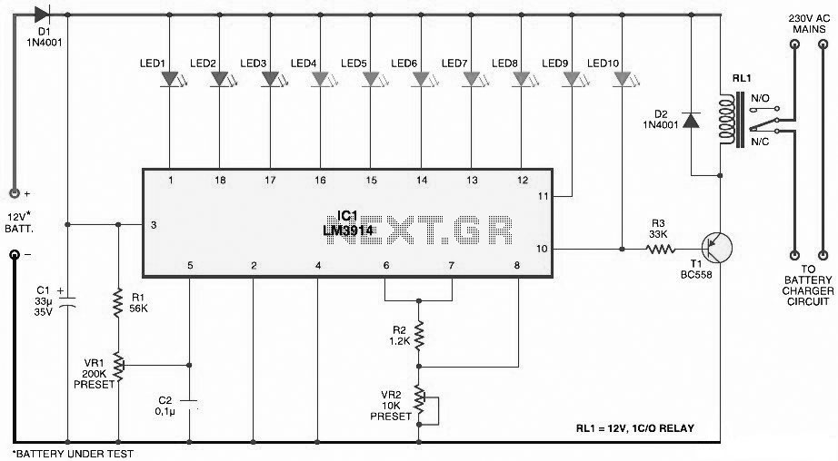
The battery level indicator circuit is designed to visually represent the remaining charge in a battery, commonly used in portable devices such as mobile phones. The circuit generally employs a series of LEDs to indicate different levels of battery charge. For example, a common configuration may include three LEDs, which light up in sequence as the battery voltage decreases.
The circuit typically consists of a voltage divider, which scales down the battery voltage to a level suitable for the LEDs. The voltage divider is composed of two resistors, R1 and R2, connected in series across the battery terminals. The junction between the two resistors provides a voltage that varies with the battery's charge level. This voltage is then fed into a comparator or a microcontroller that determines which LED should be turned on based on the voltage level.
The LEDs are connected to the output of the comparator or microcontroller, with each LED representing a specific voltage range. For instance, if the battery voltage is above a certain threshold, the green LED may light up, indicating a full charge. As the voltage drops, the yellow LED might activate to indicate a medium charge level, and finally, the red LED would illuminate when the battery is low.
In addition to the basic components, the circuit may include a potentiometer to calibrate the voltage thresholds for each LED, ensuring accurate representation of the battery level. A resistor in series with each LED is also necessary to limit the current flowing through the LEDs, preventing damage and ensuring longevity.
Overall, this battery level indicator circuit is a straightforward and effective solution for monitoring battery status in various electronic devices, providing users with a clear visual indication of remaining power.Here the circuit diagram of simple and easy made battery level indicator. In general, in mobile phones, the battery levels is displayed in dot or bar style. This helps you to effortlessly acknowledge the battery level. On this page we provi.. 🔗 External reference
Related Circuits
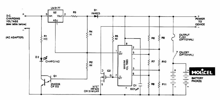
The charging system described is designed for multi-cell lithium battery packs comprising two to six series-connected cells or series/parallel configurations. The schematic diagram originates from the lithium battery charger power supply circuit. This circuit is specifically intended for charging...
This circuit is designed for liquid level or proximity detection. It operates by measuring the distance to a target through the reflection of an infrared beam. The device can detect the level of liquid in a tank without any...
Touch the sensor of the alarm with your finger, and it starts beeping. It continues for a period and then stops. Touching it again will activate the beeping once more. This description outlines a basic touch-activated alarm system. The...
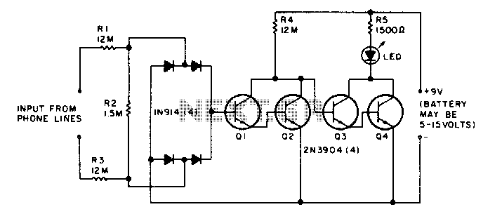
The LED flickers when the phone is ringing or being dialed. It glows steadily when the phone is off the hook. The described circuit involves an LED indicator that serves two primary functions based on the state of the phone....
This is a simple oscillator with multiple resistors in series. When you press any switch, the circuit starts oscillating. You can use variable resistors instead of the 1k resistors. Using variable resistors, you will be able to tune the...
This is a dry cell battery charger circuit designed to charge batteries over a period of approximately 12 hours. When powered by a 9-volt supply, the circuit is configured to accommodate AA-sized batteries. If C or D-sized batteries are...