
mini drill speed regulator
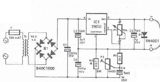
The described circuit utilizes an integrated voltage regulator to control the speed of a mini drill motor effectively. The configuration allows for a variable output voltage that can be tailored to the specific requirements of different motors within the defined voltage range. The critical components include the voltage regulator (79GU), resistors R1 and R2, and the potentiometer P2.
In this setup, R1 and R2 form a voltage divider that sets the output voltage. The formula Uout = (R1 + R2) Uc/R2 indicates how the output voltage is influenced by the resistance values. Adjusting R1 or R2 will change the output voltage accordingly. The potentiometer P2 acts as a variable resistor, allowing for fine-tuning of the coupling degree, which directly affects the output voltage and consequently the motor speed.
Thermal management is essential in this circuit. The voltage regulator is equipped with thermal protection to prevent overheating, which is critical when operating at higher currents. Proper sizing of the heatsink is necessary to dissipate heat effectively, ensuring reliable operation over extended periods.
Overall, this circuit provides a versatile solution for controlling the speed of mini drill motors, accommodating various operational demands while ensuring consistent performance and safety through thermal management.With an integrated voltage regulator connected reverse to a mini drill can be adjusted speed within certain limits so that it remain constant, independently of load. In the scheme presented below the electronic speed control is made by a voltage regulator, allowing use of motor which require a supply voltage from 2.
5 V to 12 V at a maximum current absorbed by an 1A. Output voltage is determined by the ratio of resistances R1 and R2. Uout = (R1 + R2) Uc/R2. Uc is equal to -2. 23 V for 79GU voltage regulator. With the P2 potentiometer can be adjusted the degree of coupling (coupling the output voltage increases with increasing output current). Thus remains constant preset speed. Maximum voltage measured when the P2 is turned up must be about 20% lower than the maximum allowable voltage of the motor (if is not, the value of R1 should be reduced or enlarged accordingly).
Voltage regulator is designed with thermal protection, but it must be mounted on a properly dimensioned radiator. 🔗 External reference
Related Circuits
The ISL5929 is a dual 14-bit, 130/210+ MSPS (Mega Samples Per Second), CMOS, high-speed, low-power, digital-to-analog converter (DAC) designed specifically for high-performance communication systems, such as base transceiver stations utilizing 2.5G or 3G cellular protocols. The ISL5929 DAC is engineered...
Typically, the study of electronic power supplies starts with batteries, such as 9 volts, 1.5 volts, and 6 volts. However, there are disadvantages associated with this approach. The exploration of electronic power supplies often begins with the use of batteries,...
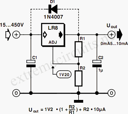
Commonly used 3-pin linear voltage regulators, such as the LM317, cannot handle input voltages exceeding approximately 30V. The LR8A from Supertex Inc is a new adjustable three-pin regulator capable of accepting input voltages up to 450V and supplying an...

This is a Variable Voltage Regulator Circuit built using the LM317T integrated circuit (IC). The LM317T is an adjustable three-terminal positive voltage regulator capable of supplying more than 1.5 amps over an output range of 1.25 to 37 volts....
This circuit is a mini bicycle bell. The mini bicycle bell is activated by a switch that functions as a button. When the button is pressed, an electric current flows through a 9V electronic circuit via the transistor Q1....
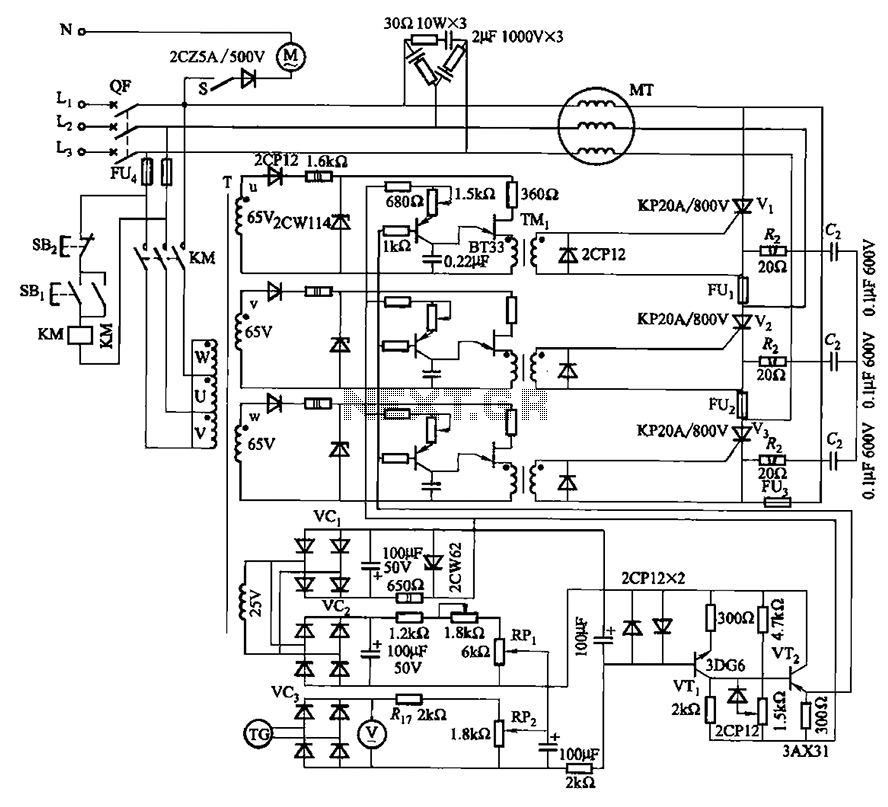
The circuit depicted in Figure 3-181 comprises three thyristors, labeled V1 to V3. The trigger circuit utilizes a single-junction transistor relaxation oscillator. The speed control circuit incorporates negative feedback. A master adjust potentiometer, designated as RPi, is used to...