
3 phase sinewave generator
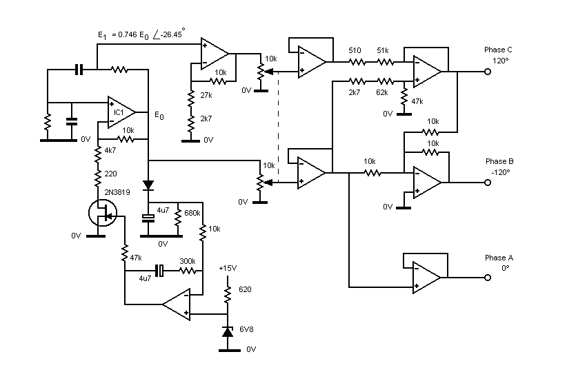
This circuit utilizes a Wien oscillator configuration, which is renowned for its ability to generate sine waves with high stability and low distortion. The operational amplifiers in the circuit serve as the core active components, providing the necessary gain and phase manipulation. The Wien oscillator consists of a feedback network made up of resistors and capacitors that determine the frequency of oscillation. The phase relationship between the output of the oscillator and the feedback junction is critical, as it dictates the stability of the oscillation.
In this modified version, the removal of preset potentiometers simplifies the design while still allowing for adequate control of output characteristics through fixed resistors. The choice of resistors in series allows for a more stable configuration, reducing variability introduced by mechanical components. The slight variations in output amplitude and phase due to the mechanical play in the potentiometer are acknowledged but deemed acceptable for the circuit's application, which does not require precision adjustments.
The operational amplifiers are configured in a way that ensures the output signals are coherent and maintain the desired phase relationships. The careful selection of resistor values is essential to achieving the desired frequency response and output characteristics. This design emphasizes reliability and ease of use, making it suitable for applications where minor variations in output are permissible. Overall, the circuit effectively demonstrates the principles of oscillation and phase control, providing a functional solution for generating stable sine wave outputs.I would have assumed that anyone interested in building one of these would have a reasonable understanding of electronics in general and the use of operational amplifiers in particular. This circuit relies on the fact that the phase difference between the output of a Wein oscillator and the junction of the CR in the series feedback is constan
t, regardless of the oscillation frequency. Phases are derived from adding appropriate magnitudes and signs of voltages obtained from these two. It is my version of a circuit I came across in commercially built equipment. The original had a few pre-set pots so one could adjust the amplitudes of and phase differences between the outputs. The pots have been eliminated by using two resistors in series in a couple of places. Due to a bit of lost motion between the shaft and rear section of the dual amplitude-setting pot, there is a very small variation in the amplitudes and phases of the outputs as the direction of rotation is changed.
This would have made a total nonsense of using the afore-mentioned pre-sets. It is of no consequence in the application for which it was built, but is a bit disappointing in a pot of this pedigree (Bourns). 🔗 External reference
Related Circuits
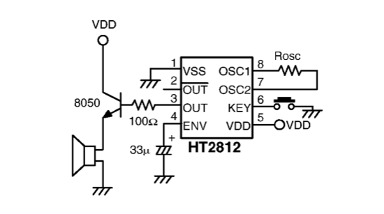
A sound generator is needed for a room monitoring system. Suggestions for an electronic design are requested, as the HT2810 or similar components are not preferred. The sound generator circuit for a room monitoring system can be designed using a...
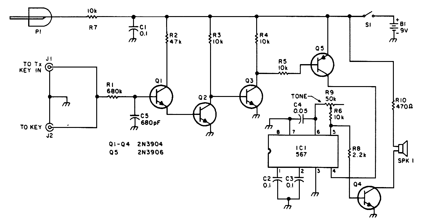
This circuit is designed for low-power transmitters that operate with a positive keying voltage. The transistors Q1, Q2, and Q3 are configured as a switching amplifier. When the key is pressed, the collector of Q3 connects to ground, which...

This design circuit features a simple, cost-effective amplitude-stabilized phase-shift sine wave oscillator that requires one integrated circuit (IC) package, three transistors, and operates from a single power supply. The circuit incorporates an RC network configured for phase shift, oscillating...

The two most common motor control methods are DC Chopper control and Phase Angle control. This article explores the differences between the two methods, identifying some key trade-offs that can be useful for motor control designers when determining the...
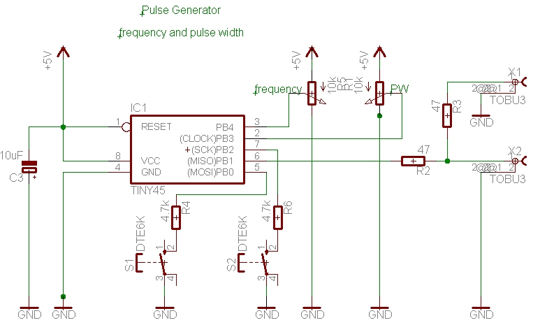
A simple pulse generator with a variable duty cycle and frequency is often useful in the lab to trigger or test other devices, such as a servo with a frequency of 50 Hz and pulses between 1 and 2...
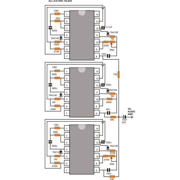
This document discusses a compact machine gun sound effect generator circuit. Once constructed, it can be integrated with any audio amplifier to create a realistic war-like simulation. This small hobby project is suitable for all electronics enthusiasts and generates...