
phase shift oscillator circuit

The circuit operates by generating a stable sine wave output through a combination of phase-shifted feedback and amplitude stabilization. The phase shift is achieved using a network of resistors and capacitors that create the necessary delay for oscillation. The frequency of oscillation, approximately 12 kHz, is determined by the values of the resistors and capacitors in the RC network, allowing for adjustments based on component selection.
The LM386 operational amplifier is integral to the circuit's function, providing amplification with a fixed gain, which simplifies design considerations. The 10 µF capacitor in series with the 1M resistor serves to couple the output from Q2 to the LM386 input while blocking any DC offset, ensuring only the AC component of the signal is amplified.
The rectification process at the output of the LM386 converts the AC signal into a DC voltage, which is stored in the 5 µF capacitor. This stored voltage is crucial for controlling the base of Q3, allowing it to modulate the current that flows through Q1. The emitter follower configuration of Q1 ensures that the oscillator is driven with a stable voltage, thereby enhancing the overall stability of the sine wave output.
In summary, this circuit exemplifies an efficient design for generating a stable sine wave output using minimal components, making it suitable for various applications where a reliable signal source is required. The careful selection of components and their arrangement within the circuit ensures both amplitude stability and frequency accuracy.This is a design circuit of a simple inexpensive amplitude stabilized phase shift sine wave oscillator which requires one IC package, three transistors and runs off a single supply. This circuit is combination with the RC network comprises a phase shift configuration and oscillates at about 12 kHz.
The remaining circuitry provides amplitude stabil ity. Here`s the schematic figure of the circuit. The high impedance output at Q2s collector is fed to the input of the LM386 via the 10 F-1M series network. This circuit is using op amp LM386 causes it has fixed gain of 20. The 1M resistor in combination with the internal 50 k © unit in the LM386 divides Q2s output by 20. The positive peaks at the amplifier output are rectified and stored in the 5 F capacitor. This potential is fed to the base of Q3. Q3s collector current will vary with the difference between its base and emitter voltages. Since the emitter voltage is fixed by the LM313 1. 2V reference, Q3 performs a comparison function and its collector current modulates Q1s base voltage.
Q1, an emitter follower, provides servo controlled drive to the Q2 oscillator. 🔗 External reference
Related Circuits
Electronics Circuits Reference Archive Audio preamplifier circuits. There are thousands of preamplifier circuits. Here are three that are somewhat different and have garnered interest. Intercom preamp: A very convenient way of making an intercom system. Audio preamplifiers are essential components...
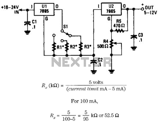
This voltage regulator and current limiter combination can be constructed using two 7805 regulators as illustrated. Resistors R1, R2, and R3 should be chosen to achieve a 5-V drop at the maximum allowable current limit. Switch S1 selects one...
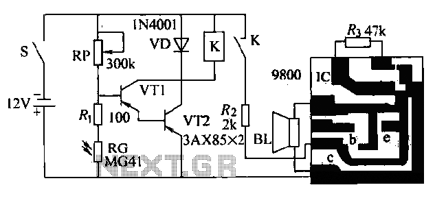
The circuit presented is a second-generation flame alarm for natural gas stoves. After the gas stove is ignited and normal combustion occurs, the power switch S is closed. The photoresistor RG, influenced by the light from the flame, has...

This is a simple hobby circuit for a remote-controlled toy car. The primary component utilized is the IR sensor circuit, which includes a TSOP IR receiver. This receiver allows the user to start and stop the DC motor of...
This simple circuit is the electronic version of the combination lock. Using the special purpose LS7220 digital lock IC, the circuit allows a 4 digit combination of your choice to activate a relay for a set period of time....
This flip-flop circuit functions as a free-running astable multivibrator, where the bases and collectors of both emitter-biased transistors are directly coupled. The switching action is facilitated by a capacitor in each emitter circuit, resulting in the generation of triangle...