
3 volts car adapter using lt1074ct
The LT1074CT is a versatile switching regulator capable of efficiently converting higher DC voltages to lower ones, making it ideal for applications requiring stable voltage supplies from car batteries. The buck converter topology employed in this design allows for high efficiency and reduced heat generation, which is critical in automotive applications where space and thermal management are concerns.
The feedback mechanism is crucial in ensuring that the output voltage remains stable despite variations in load conditions. The resistors R1, R2, and R3 form a voltage divider that feeds back a portion of the output voltage to the F/B pin, allowing the LT1074CT to adjust its duty cycle accordingly. This feedback loop is essential for maintaining the desired output voltage of +3 V, regardless of fluctuations in input voltage or load current.
Inductor L1 plays a vital role in energy storage during the switching process. As the LT1074CT switches on, current flows through L1, storing energy in the magnetic field. When the switch turns off, the inductor releases this stored energy to the output capacitor C1 and the load, ensuring a continuous supply of current. The choice of inductor value is critical, as it affects the ripple current and overall efficiency of the converter.
Capacitor C1 not only serves to decouple the output load but also smooths out voltage fluctuations, ensuring a stable output voltage. The input capacitor C3 is equally important, as it helps filter out high-frequency noise and provides a stable voltage to the LT1074CT, enhancing the overall performance of the circuit.
In summary, this circuit provides an effective solution for powering low-voltage devices from a car's electrical system, ensuring that children can use their devices without concern for battery life or voltage stability during long journeys. The design emphasizes efficiency, stability, and safety, making it a practical choice for automotive applications.This circuit is based on a standard LT1074CT switching regulator IC. For sure, Application Note AN35 published by Linear Technology describes the design far more elegantly than the author could in this short article. Interested readers are therefore strongly advised to get a copy of AN35. The schematic shows the LT1074CT used as a positive step-do wn or buck` converter. The switcher` is used to convert a +12-volt car battery voltage down to +3 volts for use with the personal hi- ¬`s and hand-held games for the author`s two boisterous children on long car journeys. Note at under ten years of age, children will rarely be hi- ¬ a ¬cionado`s and are generally not concerned with any noise generated by the switcher circuit.
The circuit is connected to the car +12-V system via the cigarette lighter socket ” is advisable to use a fused version of the cigarette lighter plug. The +12-V arrives on the board via screw- terminal block J2. Diode D2 provides a reverse voltage protection, while C3 decouples the input to the switcher IC. The LT1074CT briskly switches the supply voltage on and off in response to the signal applied to its F/B input, to the extent that the average output voltage is at the required level.
The values of potential divider resistors R1-R3 have been chosen to attenuate the output voltage so that there is 2. 5 V at the F/B pin. The difference between the attenuated output voltage and the internal 2. 5-V reference is used to control the modulation effect of the switcher. Components R2 and C2 provide frequency stabilization for the feedback loop. Inductor L1 along with the LT1074CT form the main switching components, while C1 provides decoupling for the output load.
The 3-V output voltage is taken from screw terminal J1. With this circuit built, boxed up and installed in your car, you can look forward to possibly your first quiet` long car journey. 🔗 External reference
Related Circuits
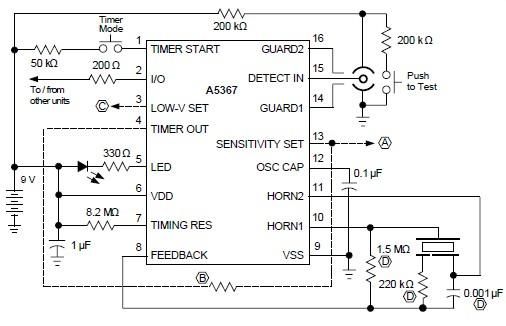
A simple ionization smoke detector with interconnect and timer alarm circuit can be constructed using the A5367 low-current, CMOS circuit, which provides all essential features for an ionization-type smoke detector. This CMOS IC, manufactured by Allegro MicroSystems, includes interconnect...
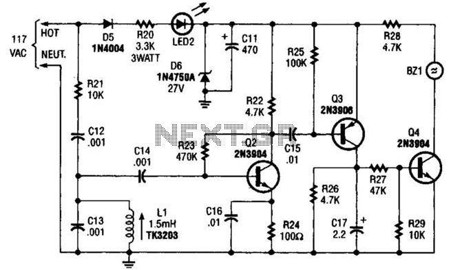
The baby-alert receiver consists of three transistors: Q2, configured as a high-gain linear amplifier; Q3, functioning as both an amplifier and detector; and Q4, which operates primarily as a switch. Additionally, there are several other components involved. The system...
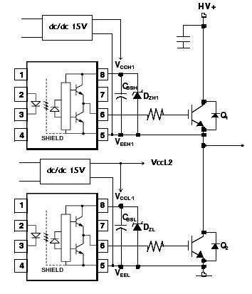
An H-bridge circuit has been developed utilizing four floating gate drivers and four insulated gate bipolar transistors (IGBTs). The attached schematic illustrates one half of the H-bridge configuration. The circuit operates effectively, but there are additional considerations to address. The...
Introduction The ignition timing lights commonly used range from simple neon to complex units. Neon timing lights have a drawback due to their low light output, necessitating operation in subdued lighting. This presents a safety hazard, as users tend...
This circuit is a dual voltage regulated power supply, +12, -12, 0 volt. It uses the 7812 and 7912 regulators. You need a 18VCT, 1A transformer at input. More: Caution: Input / Ground are reversed between the 7812 and...
The capacitance between the wire and the probe would form a capacitive voltage divider with the probe's input capacitance, and at frequencies significantly higher than the low frequency roll off created by the probe's input capacitance and the probe's...
Warning: include(partials/cookie-banner.php): Failed to open stream: Permission denied in /var/www/html/nextgr/view-circuit.php on line 713
Warning: include(): Failed opening 'partials/cookie-banner.php' for inclusion (include_path='.:/usr/share/php') in /var/www/html/nextgr/view-circuit.php on line 713