
Dimmer Using The Z8 Microcontroller

The ignition timing light circuit utilizes a xenon stroboscopic tube, which is advantageous due to its high light output, making it suitable for use in various lighting conditions. The circuit is designed to operate at high voltages, with the inverter generating the necessary voltage levels for the xenon tube to function correctly. The inverter's flyback operation is critical, as it allows for efficient energy transfer and protects the switching transistor from excessive stress during operation.
The transformer T1 plays a pivotal role in voltage conversion and energy transfer. Its design must accommodate the high-frequency operation of the inverter while ensuring that the energy is effectively transferred to the xenon tube. Capacitors C10 and C11 must be selected based on their capacitance values to achieve the desired brightness of the flash. Larger capacitance values will yield a more intense flash, while the voltage rating must exceed the maximum voltage the circuit will encounter.
The control mechanism for the switching transistor Tr7 is implemented via a Schmitt trigger configuration using transistors Tr3 and Tr4. This configuration allows for precise control of the timing and duration of the energy discharge into the xenon tube. The feedback loop created by R11 ensures that the circuit can adapt to varying load conditions, maintaining consistent performance.
Overall, this ignition timing light circuit represents a sophisticated solution for automotive applications, providing safety and efficiency through its high-intensity light output and robust design. It can also be adapted for additional applications, such as low-power stroboscopic lighting, with minimal modifications to the existing circuit.Introduction The ignition Timing lights in common use range from simple neon to complex units. Neon Timing lights have a drawback that due to their low light output, the user is forced to operate them in subdued lighting. This becomes a safety hazard as one tends to hold the unit close to the Timing mark and to the invisible (or apparently stat
ionary) fan blades. The ignition lights which use Xenon filled stroboscopic tubes are much better, since their light output is of much higher intensity. The circuit described in this note incorporates such a tube, which has an anode voltage rating of 500 volts maximum and requires a trigger voltage between 2-6kV.
The circuit was designed for a four stroke engine. It will be seen later that the unit CAN be converted for use as a low power stroboscope with some slight modifications. The required high voltage for the tube was achieved by using an inverter. The inverter must drive a capacitive load and also withstand the secondary being shorted. Operating the inverter in the flyback mode seemed the best choice, since the energy transfer only takes place when the switching Transistor is off, thus effectively isolating it from the load.
Circuit Action In the circuit diagram shown in Figure 1, the Transistor Tr7 is the switching device. The transformer T1, converts the voltages and also transfers the energy. The capacitors C10 and C11 are used as energy storage elements. When the tube is triggered, this stored energy is discharged into the tube - which produces a bright Flash of light. The brightness of the Flash depends on the size of the storage capacitors and the voltage to which they are charged.
The switching of Tr7 is controlled by the Schmitt Trigger formed by Tr3 and Tr4, which senses the `current` through the primary and secondary. On Switch on, the Transistor Tr3 will be off and Tr4 will be on. Thus, turning on Transistor Tr5 pulls the Gate of the MOSFET Transistor up to approximately the supply voltage.
Whilst the MOSFET is on, the energy is stored in the primary inductance of the transformer. The current in the primary increases as a linear ramp whose slope is inversely proportional to the primary inductance. The resistor R11 senses this 🔗 External reference
Related Circuits
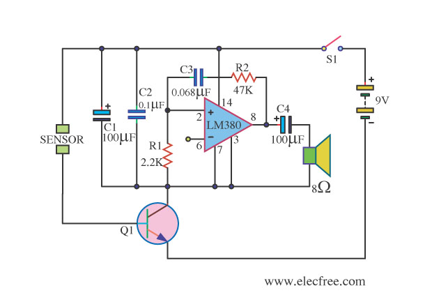
This is a water sensor alarm circuit designed to warn users about water levels. It activates an audible alarm when the sensor comes into contact with water, such as during rainfall. The water sensor alarm circuit functions primarily as a...

As found in SLAA458, the revised pulse oximeter application, an image of the USB schematic is attached, which is used to output collected data. There are a few questions regarding this schematic: 1) What do J3 and J6 correspond...
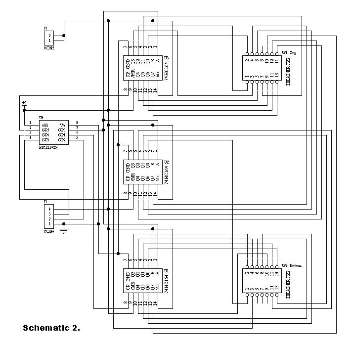
Communication with the MCP3028 ADC chip is achieved through a straightforward serial interface that adheres to the SPI protocol. The PIC16F84 or PIC16F628 does not possess a hardware SPI peripheral. However, a software-implemented SPI protocol can facilitate communication with...
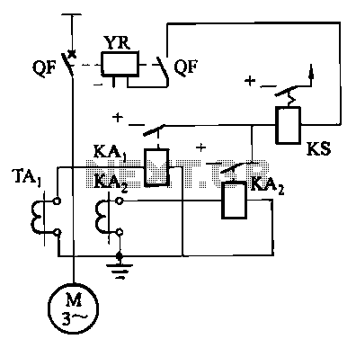
Figure 4-52 (a) illustrates the two-phase wiring for direct current (DC) operation, while Figure 4-52 (b) depicts the two-phase current differential wiring for alternating current (AC) operation. The schematic in Figure 4-52 (a) represents a two-phase wiring configuration suitable for...

A microcontroller (MCU) is a compact computer integrated into a single circuit, comprising a relatively simple CPU along with supporting functions such as crystal oscillators, timers, sensors, and serial and analog input/output (I/O). Microcontrollers are designed for small-scale applications,...
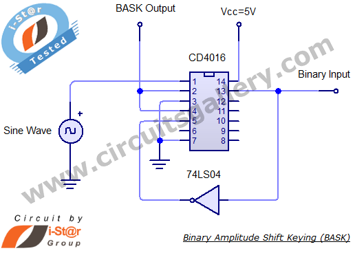
Binary Amplitude Shift Keying (BASK), also known as On-Off Keying (OOK), is a digital modulation technique where the amplitude of the carrier signal is altered according to binary data. This modulation scheme is utilized for transmitting digital information over...