
Carrier-Current Baby-Alert Receiver Circuit

The baby-alert receiver circuit is designed to monitor and respond to specific frequency signals, providing an effective alert system for caregivers. The core of the circuit involves three transistors, each serving a distinct purpose to achieve optimal performance.
Transistor Q2 is configured as a high-gain linear amplifier, which amplifies the incoming signal to a sufficient level for further processing. This amplification is critical, as it ensures that even weak signals can be detected and processed effectively. The high-gain configuration allows for minimal distortion, preserving the integrity of the signal.
Transistor Q3 operates in dual capacity as both an amplifier and a detector. In its amplifier role, it further boosts the signal received from Q2, ensuring that it is strong enough for detection. As a detector, Q3 identifies the presence of the specific 125-kHz signal emitted by the alarm transmitter. This dual functionality is essential for the circuit's ability to discern the intended alarm signal from potential noise present in the environment.
Transistor Q4 acts as a switch, controlling the activation of the alarm (BZ1). When Q3 detects the 125-kHz signal, it triggers Q4, which completes the circuit to the alarm. This switching mechanism allows for immediate response to the detected signal, ensuring that the alarm is sounded promptly to alert caregivers.
The additional components in the circuit may include resistors, capacitors, and diodes, which work together to stabilize the circuit, filter out noise, and protect the transistors from voltage spikes. The inclusion of these components is vital for the reliability and longevity of the baby-alert receiver.
The system operates by receiving the 125-kHz signal through the existing 120-V power lines, which serves as a convenient method for signal transmission without requiring additional wiring. This feature enhances the practicality of the baby-alert receiver, making it suitable for various applications in monitoring and alert systems. Overall, the design emphasizes efficiency, reliability, and responsiveness, making it an effective solution for alerting caregivers to the presence of an alarm condition. The baby-alert receiver is comprised of three transistors: Q2, which is configured as a high-gain linear amplifier; Q3, which serves as both an amplifier and detector; and Q4. which is essentially used as a switch; and a few additional components. It sounds an alarm BZ1 on receipt of a 125-kHz signal from an alarm transmitter via the 120-V power lines. 🔗 External reference
Related Circuits
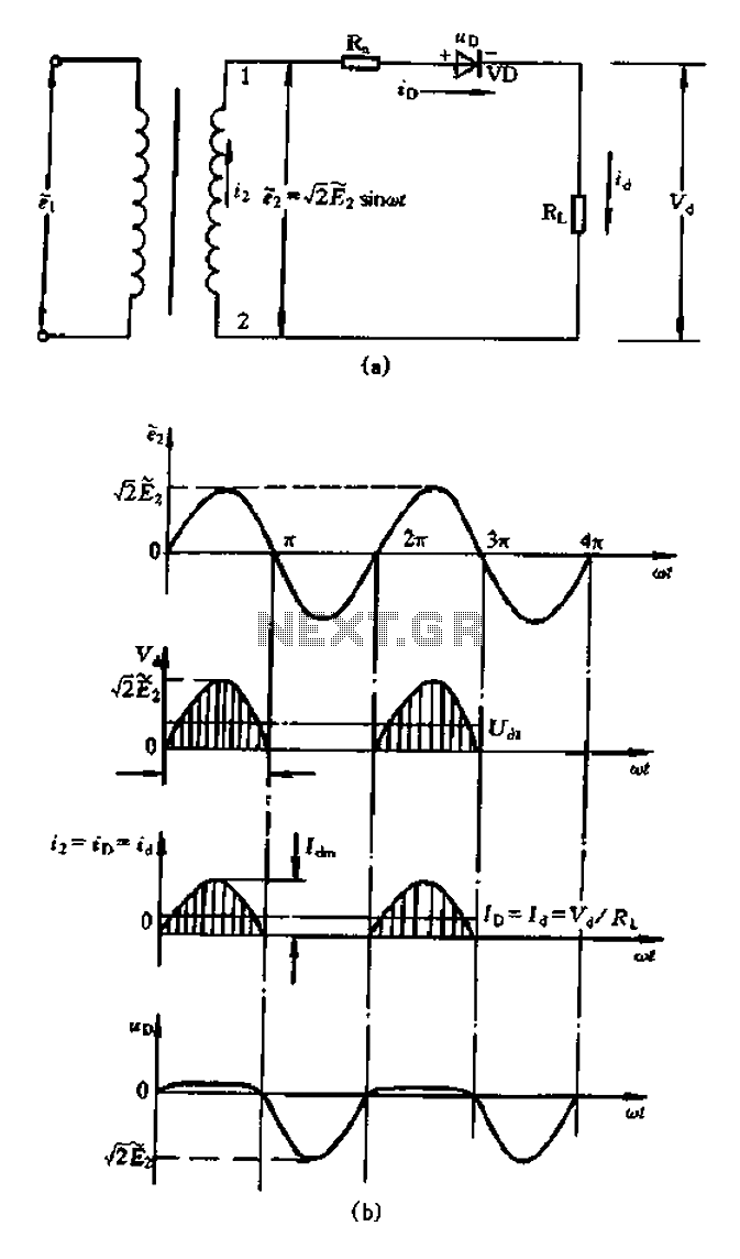
A bridge rectifier capacitor filter serves as a primary power supply for current amplifier circuits. This power supply configuration is straightforward and offers enhanced performance. The bridge rectifier circuit is a full-wave rectifying circuit, meaning it converts both the...
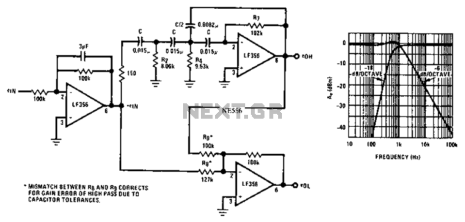
Asymmetric third-order Butterworth active crossover network circuit diagram. The asymmetric third-order Butterworth active crossover network is a sophisticated circuit designed to split an audio signal into two separate frequency bands, typically for use in multi-way speaker systems. This type of...
The metal detector circuit consists of several key components including the probe oscillator, reference oscillator, oscillation signal processor, mixing amplifier, and ammeter PA. The probe oscillator is made up of the oscillating tube VI, exploration coil L1, capacitors C1...

The motors will be powered by the full source voltage, so it is important to ensure that this does not cause the robot to operate too quickly. The Firebot utilizes GM3 motors powered by a 9V battery; however, in...
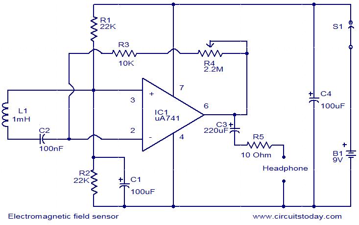
This is a very simple circuit that can be used to sense electromagnetic radiations. The circuit can even detect hidden wires. A 1mH inductor is used for sensing the electric field. The electric field will induce a small voltage...
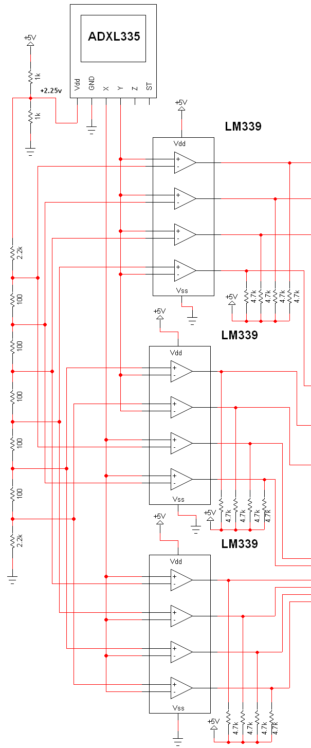
The schematic for this project is extensive, and the complete schematic is displayed below. It is divided into two sections: the analog and digital sections. The schematic illustrates the analog-to-digital conversion circuit, which includes 12 comparators—6 for the X-axis...