
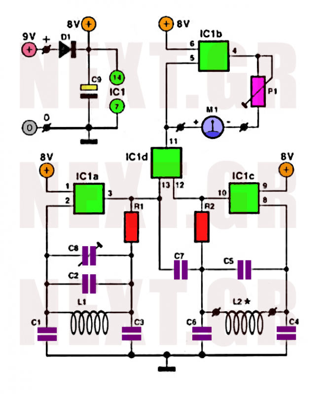
300kHz signal generator circuit

Component selection includes: Transistor VT1: 3DG6C, with a gain range of 65 to 85; Diodes VD1, VD2: 2CPl4; VD5: 2CK18; Zener diode VD3: 2CWl4; Variable capacitance diode VD4: 2CC5. Resistors are specified as R1: 3.6k, R2: 3.3k, R3: 5.1k, R4: 510Ω, R5: 3.9k, R6: 3k, R7: 100k, with models RTX-0.125W. Capacitors include C1, C2: 5 µF 30V; C3: 51 pF 100V; C4: 820 pF 100V; C5: optional; C6: 20 pF. The variable filter T1 is of model L22, with an inductance of A = 100. Windings L1-4 use 0.29 mm wire, with approximately 27 turns for L1-3, 18 turns for L2-3, 9 turns for L4-2, 7 turns for L5-8, and 6 turns for L6-7. The total inductance for L1-3 is 292 µH, with a tolerance range of 0 to 10 µH.
The 300 kHz signal generator operates by utilizing a varactor diode (VD4) to modulate the capacitance in response to a negative control voltage. This modulation allows fine-tuning of the oscillation frequency, which is critical for applications requiring precise signal generation. The oscillator circuit's stability is enhanced by the Zener diode (VD3), which regulates the voltage to maintain consistent performance across varying conditions.
The inductive components, particularly the transformer T1, play a crucial role in the signal generation process. The specified winding configurations and wire gauges are designed to optimize performance while minimizing losses. The selection of high-quality capacitors and resistors ensures reliability and accuracy, which are essential for generating a stable 300 kHz signal.
In summary, this circuit design integrates a variety of components to achieve effective signal generation with adjustable frequency characteristics, making it suitable for various electronic applications where precise oscillation is required.Shown for the 300kHz signal generator. It consists VT1, T1, VD4 composition VCO and associated components. VCO using LC tuned collector, VTl the oscillating tube, varactor diode VD4, T1 1-3 inductive winding capacitance C3 ~ C6 and variable tuning circuit composed varactor VD4 anti-bias work from a negative voltage is applied to the control terminal, to change its capacitance. An oscillation signal output from the winding Tl 6-7. Wherein, C6 is the frequency tuning capacitor. VD3 stable oscillator stage operating voltage, stable voltage of 6.8V 0.2V.Component selection: Transistor VT1: 3DG6C, = 65 ~ 85.
Diodes VD1, VD2: 2CPl4, VD5: 2CK18. Zener diode VD3: 2CWl4. Variable capacitance diode VD4: 2CC5. Resistance R1: 3.6k, R2: 3.3k, R3: 5.1k, R4: 510, R5: 3.9k, R6: 3k, R7: 100k, which models are RTX-0.125W. Capacitors Cl, C2: 5 F30V, C3: 51pFl00V, C4: 820pFl00V, when commissioning C5 :( optional), C6: 20pF.
Variable filter T1: Model L22, A = 100. L1-4: µ0.29mm, around the 27-turn, L2-3: µ0.29mm, turns around l8, L4-2: µ0.29ram, around 9 turns, L5-8: µ0.29mm, around 7 turns, L6- 7: µO. 29mm, about 6 turns. L1-3 = 292 H, tolerance range: 0 ~ 10 H.
Related Circuits
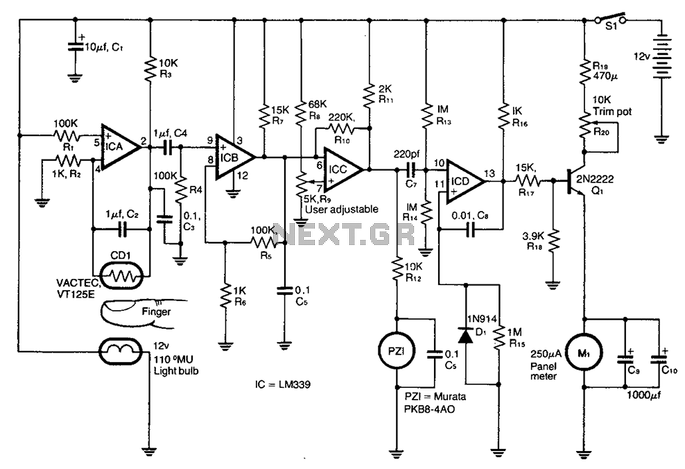
A cadmium sulfide photoresistor (CD1) fingertip can be detected through the filter. CD1 forms part of the sense amplifier feedback network. A section of the sense amplifier (ICA) produces weak signals that may be further amplified by ICB. These...
This circuit generates a two-tone effect similar to the cuckoo song. It can be used for doorbells or other applications due to a built-in audio amplifier and loudspeaker. As a sound effect generator, it can be connected to external...

This series-feedback configuration of components provides a high input impedance and stable, wide-band gain video amplifier suitable for general-purpose applications. Below is the schematic representation of the circuit. The described video amplifier circuit employs a series-feedback topology, which is instrumental...
Precious metals can sometimes be buried too deep to be detected without complex devices. However, smaller pieces of precious metals located near the surface can often be found using simpler methods. Many individuals are drawn to the prospect of...
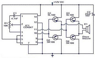
The circuit operates on the principle that insects, such as mosquitoes, can be repelled using sound frequencies in the ultrasonic range (above 20 kHz). It utilizes a Phase-Locked Loop (PLL) integrated circuit, specifically the CMOS 4047, configured as an...
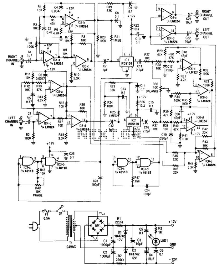
Right- and left-channel signals pass through buffer amplifiers C4-a and C4-b into the active crossover IG5. Low frequencies are directed to mixer IC6-c, while middle and high frequencies are sent to analog delay lines 1C1 and 1C2. The output...