
Cuckoo Sound Generator Circuit Schematic
This circuit design incorporates various components to effectively generate and manipulate sound waves for a specific auditory effect. The use of a square wave generator (IC1) allows for the creation of distinct frequencies, while the trimmers (R2 and R22) provide fine-tuning capabilities to achieve the desired pitch. The conversion of the square wave into a quasi-sinusoidal waveform ensures a more pleasant sound output, enhancing the overall quality of the generated tones. The incorporation of noise generation (Q1 and R6) adds a layer of complexity to the sound, making it more engaging.
The functionality of Q2 as a mixer and gate is crucial for controlling the sound's dynamics, ensuring that the resulting audio output has the desired attack and decay characteristics. The audio power amplifier (IC4) is essential for driving the loudspeaker, allowing the sound to be heard clearly, while the volume control (R15) provides user-adjustable loudness.
The timing and sequencing of the sound generation are managed by the clock generator (IC2A) and the decade counter (IC3). This arrangement allows for versatile operation modes, giving users the option for continuous playback or one-shot sounds with each activation. The gating mechanism involving IC2C and IC2D ensures that the sound generation is synchronized with the desired timing, providing a cohesive auditory experience.
In summary, this circuit is a well-designed sound generator that combines various electronic components to create a recognizable two-tone effect reminiscent of a cuckoo song. Its versatility allows for multiple applications, from simple doorbell sounds to more complex interactive audio experiences, making it an excellent choice for hobbyists and engineers alike.This circuit generates a two-tone effect very much alike the cuckoo song. It can be used for door-bells or other purposes thanks to a built-in audio amplifier and loudspeaker. Used as a sound effect generator it can be connected to external amplifiers, tape recorders etc. In this case, the built-in audio amplifier and loudspeaker may be omitted an d the output taken across C8 and ground. There are two options: free running, when SW1 is left open, and one-shot, when SW1 is closed. In this case a two-tone cuckoo song will be generated at each P1 pressing. IC1 is wired as a square wave generator and produces both tones of the cuckoo song. The frequency of the higher one (667Hz) is set by means of Trimmer R2. When IC2D output goes low, a further Trimmer (R22) is added to IC1 timing components via D6, and the lower tone (545Hz) is generated. To imitate closely the cuckoo song, the square wave output of IC1 is converted to a quasi-sinusoidal wave form by R3, R4, C3 and C4, then mixed with the white noise generated by Q1, R6.
Q2 has two purposes: it mixes the two incoming signals and gates the resulting tone, shaping its attack and decay behavior by means of the parts wired around its Emitter. IC4 is the audio power amplifier driving the speaker and R15 is the volume control. The various sound and pause timings for the circuit are provided by the clock generator IC2A driving the decade counter IC3.
Some output pins of this IC are gated by IC2C, IC2D and related components to drive appropriately the sound generator and the sound gate. When SW1 is left open the circuit operates in the free-running mode and the cuckoo song is generated continuously.
When SW1 is closed, the circuit generates two tones then stops, because a high state appears at the last output pin (#11) of the decade counter IC: therefore the count is inhibited by means of D1 feeding pin #13. The circuit is reset by a positive pulse at pin #15 of IC3 when P1 is pressed. Best results will be obtained if the two tones frequencies are set precisely, i. e. 667Hz for the first tone and 545Hz for the second: in musical terms this interval is called a Minor Third.
Obviously a digital frequency counter, if available, would be the best tool to setup R2 and R22, but you can use a musical instrument, e. g. a piano or guitar, tuning-up the notes accurately by ear. Adjust R2 in order that the tone generated by the loudspeaker is at the same pitch of the reference note generated by your musical instrument.
This reference note will be the E written on the stave in the fourth space when using the treble clef. Connect R22 to negative ground and adjust it in order that the tone generated by the loudspeaker is at the same pitch of the reference note generated by your musical instrument.
This second reference note will be the C-sharp written on the stave in the third space when using the treble clef. Any kind of dc voltage supply in the 12 - 15V range can be used, but please note that supply voltages below 12V will prevent operation of the white noise generator.
An amusing application of this circuit is to use a photo-resistor in place of P1, then placing the unit near the flashing lamps of your Christmas tree. A sweet cuckoo song will be heard each time the lamp chosen will illuminate. 🔗 External reference
Related Circuits
Men often appreciate the convenience of television remote controls, which can sometimes frustrate their female partners. They tend to switch channels frequently, wanting to ensure they do not miss anything while a specific program is on. With the remote...
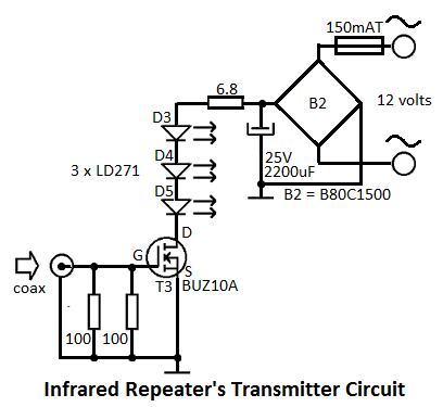
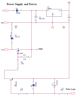
This infrared repeater system is utilized to extend the range of an infrared transmitter used with audio or video equipment up to 10 meters. The original signal is approximately. The infrared repeater system operates by receiving infrared signals from a...
This circuit is a digital panel meter (DPM) featuring an analog bar graph display and a 3.5-digit digital display. The ICL7107 is configured for 200mV input. The U4A operational amplifier (LF353) amplifies the 200mV full-scale input to the required...
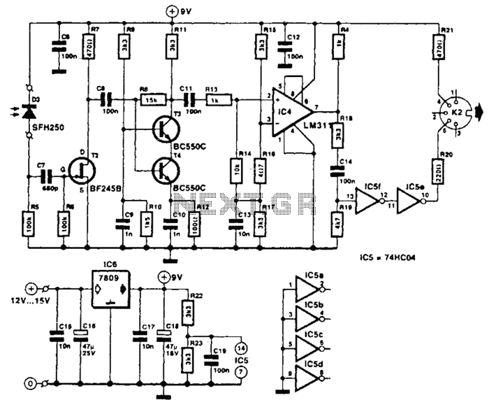
The receiver photodiode SFH250 is utilized to convert optical data pulses at a rate of 32.5 Kbps into electrical signals. The buffer T2 transmits these signals to a cascade amplifier consisting of transistors T3 and T4, followed by an...
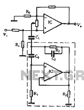
In the second equalization circuit connection method, it operates as illustrated in Figure 1-96. When the potentiometer wiper is moved to the inverting input terminal "a", the resonance impedance of the parallel combination of the feedback resistor RB reaches...
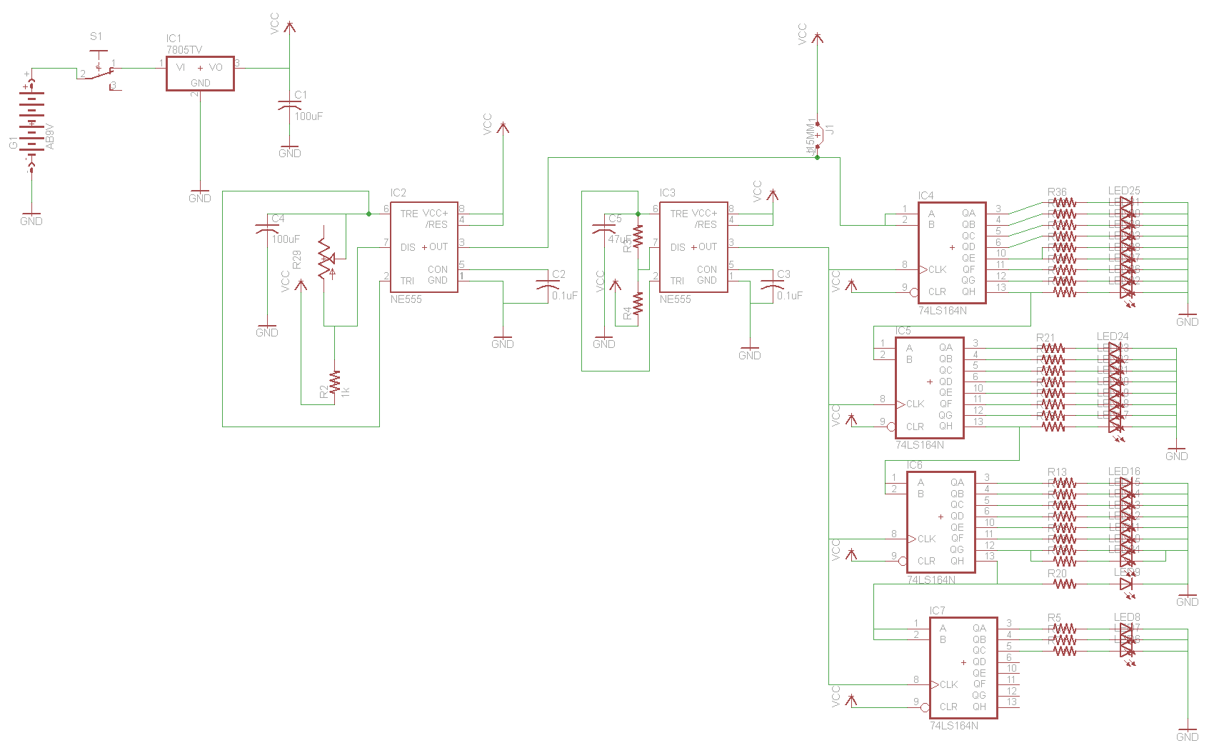
For the two-layer board schematic, six core integrated circuits (ICs) will be utilized: four 74LS164 shift registers and two 555 timers. The schematic will be constructed using the Eagle Layout Editor, as all required components are available in its...
Warning: include(partials/cookie-banner.php): Failed to open stream: Permission denied in /var/www/html/nextgr/view-circuit.php on line 713
Warning: include(): Failed opening 'partials/cookie-banner.php' for inclusion (include_path='.:/usr/share/php') in /var/www/html/nextgr/view-circuit.php on line 713