
Low Capacitance High Impedance Amplifier Circuit Using Transistor

The described video amplifier circuit employs a series-feedback topology, which is instrumental in achieving high input impedance. This characteristic is crucial for interfacing with various signal sources without loading them down. The use of feedback in the circuit enhances stability and linearity, which is essential for maintaining signal fidelity across a wide frequency range.
In this circuit, transistors or operational amplifiers are typically utilized to amplify the video signal. The configuration is designed to minimize distortion while maximizing bandwidth, making it ideal for applications such as video processing, broadcasting, and any scenario where high-frequency signals must be handled with precision.
The input stage usually consists of a high-impedance buffer that isolates the signal source from the amplifier's gain stage. This buffer stage is critical in preventing signal degradation and ensuring that the amplifier can operate effectively without introducing noise or distortion. Following the input stage, the gain stage amplifies the signal, and the feedback loop is employed to control the gain and stabilize the output.
The output stage may include additional components such as capacitors and resistors to tailor the frequency response and ensure that the amplifier can drive the desired load effectively. Overall, this series-feedback video amplifier circuit is designed for versatility and reliability in various electronic applications, ensuring high performance in video signal amplification tasks.This series-feedback series of compounds give a high input impedance and stable, gain wide-band video amplifier for general purpose applications. This is the figure of the circuit; 🔗 External reference
Related Circuits
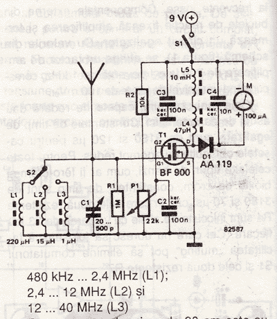
An RF field indicator is needed to verify power stages and transmitter antennas. This radio field indicator allows for the measurement of radiated energy from antennas. An RF field indicator is a crucial device in the field of telecommunications and...
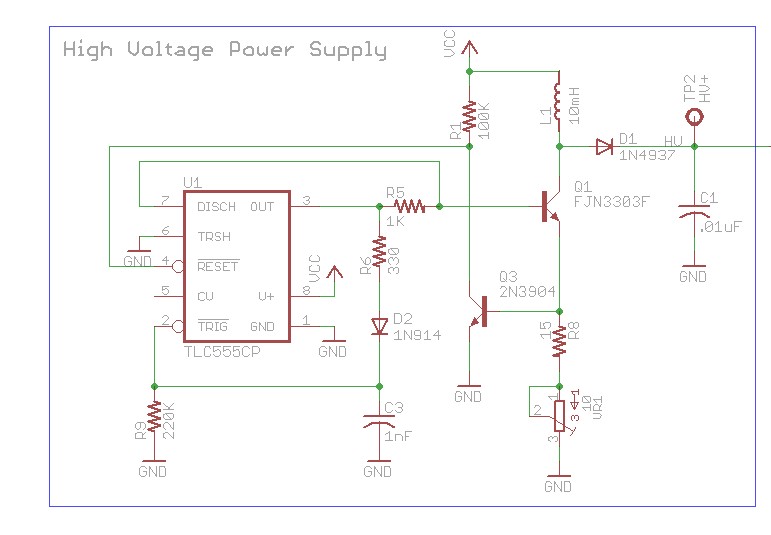
The design involves using a 555 timer as an oscillator in the high voltage power supply section. There is a query regarding the possibility of altering the design to utilize an output from a microcontroller to generate an oscillating...
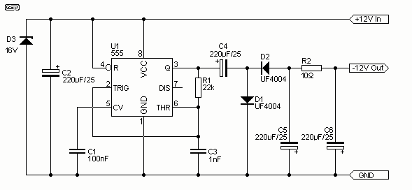
I have had a lot of queries about getting a low power negative supply in cars, to power Linkwitz transform circuits and the like. There is a switchmode converter, but I must admit that it is overkill for what...
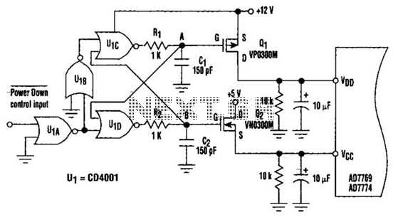
This circuit adds a power-down function to analog I/O ports, such as the AD7769 and AD7774. Additionally, the diodes typically required to protect the devices against power-supply mis-sequencing can be eliminated. In this design, MOSFETs Q1 and Q2 switch...
In a complete circuit, there are two types of elements: active and passive elements. Active elements generate energy, while passive elements dissipate energy. Examples of passive elements include resistors and capacitors. In electronic circuits, active and passive components serve distinct...
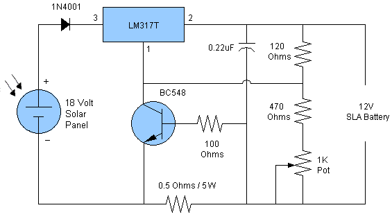
Solar battery charger schematic and description. This solar battery charger circuit is capable of charging a 12V lead-acid battery or sealed lead-acid (SLA) battery. The solar battery charger circuit is designed to convert solar energy into electrical energy for charging...