
300W Valve RF Transmitter circuit
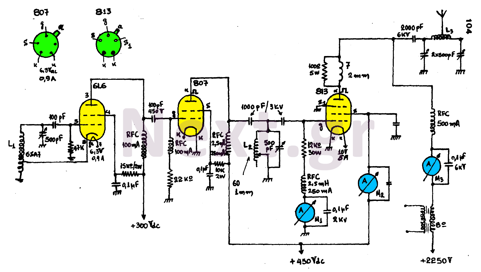
The circuit design is structured into three distinct yet interconnected stages, each serving a specific function to achieve optimal performance. The oscillator stage is critical for generating the initial signal, utilizing a 6SA7 coil as the primary inductive element. The coils L2 and L3, with their precise winding specifications, are designed to enhance the quality of resonance, which is vital for efficient signal generation. The incorporation of variable capacitors allows for fine-tuning of the resonant frequency, ensuring that the system can adapt to varying operational conditions.
The Buffer stage plays an essential role in maintaining signal integrity. By amplifying the oscillator's output, it ensures that any variations in the final stage do not adversely affect the oscillator’s performance. This isolation is particularly important in high-power applications where fluctuations can lead to instability or distortion in the transmitted signal.
The final stage, characterized by the use of an 813 power amplifier operating in class C mode, is designed for high efficiency and power output. Class C amplifiers are known for their ability to provide significant power gain while minimizing power loss, making them suitable for RF applications. The use of RFCs (Radio Frequency Chokes) is a critical design feature, as they prevent the high-frequency oscillations generated by the amplifier from interfering with the power supply and other circuit components.
Attention to construction details is paramount in this design. Long wiring runs can introduce parasitic capacitance and inductance, leading to unwanted resonances and signal degradation. Therefore, careful layout and short connections are recommended to maintain signal quality. The requirement for plug-in power transformers is also a key consideration, as it ensures that each lamp receives the appropriate voltage for optimal operation. This careful management of power supply voltages is essential for maintaining the reliability and longevity of the circuit components. Overall, this circuit design exemplifies a well-thought-out approach to RF transmission, balancing performance with practical construction considerations.It consists essentially of three stages and gives the antenna a power of 300 WATT, provided it is properly tuned. The first tier is an oscillator that has an oscillating coil L1 that will be required by the market as a 6SA7 coil.
The coils L2 and L3 consist of 60 coils of 1mm cross-section wire wound on a 5cm diameter tome so that they have some shots for better resonance, which is also done with the help of variable capacitors and ammeters. In particular, M1 must show a maximum reading while M2 and M3 have a minimum reading.
The second tier, better known as the Buffer (Buffer), is a reinforcement and isolation step together. It amplifies the signal produced by the oscillator and isolates the oscillation step from any changes in the final stage of the transmitter.
The final stage or power amplifier consists of lamp 813 and works in class C. The various RFCs used in the circuit do not allow the generated frequency Affect the feed devices.
During construction make sure you avoid long wiring that can cause unwanted vibrations. Plug-in power transformers are required to supply the lamp filaments, since both lamps are powered by 6.3V while 813 to 5V.
Related Circuits
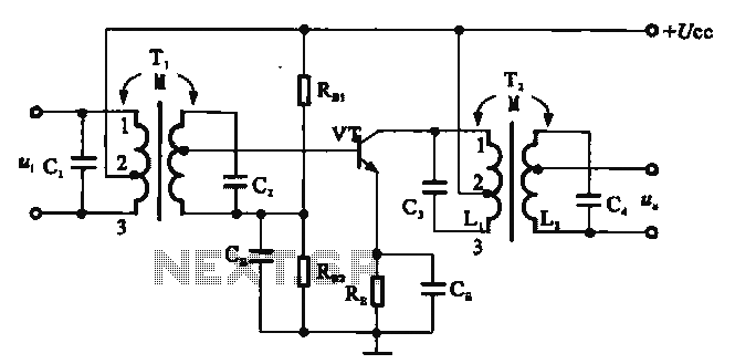
There are two resonant circuits in a double-tuned amplifier circuit, which consists of transformers T1 and T2 with primary and secondary coils that include parallel resonance capacitors. This circuit exhibits a resonance function and can be classified based on...
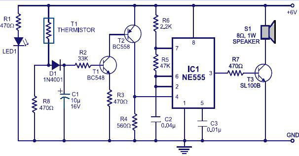
Various fire alarm circuits are discussed, featuring a new design that utilizes a thermistor and a timer. This circuit is straightforward and can be easily implemented. The thermistor exhibits low resistance at high temperatures and high resistance at low...

A 555 timer (IC1) generates a 120-Hz signal that is fed to a CD4013BE flip-flop (IC1-a), which divides the input frequency by two to generate a 60-Hz clocking frequency for the FET array (Q1 through Q6). Transformer T1 is...
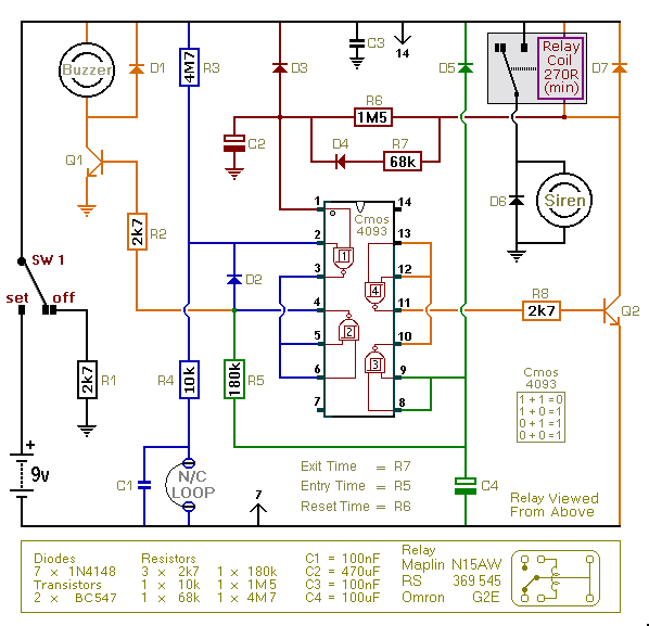
This is an improved version of the basic Garage/Shed Alarm. The Entry and Exit delays have been extended to approximately 30 seconds, and a timed Siren cut-off along with an automatic reset feature has been added. Additionally, the LED...

The voltage requirement for the Solidus is significantly higher than what your circuit currently provides. The Solidus device operates at a voltage level that exceeds the specifications of the existing circuit. To accommodate this requirement, circuit modifications will need to...

The L620x is a monolithic full bridge switching motor driver implemented using the new Multipower-BCD technology. This technology enables the integration of multiple isolated DMOS power transistors along with mixed CMOS/bipolar control circuits. The L620x series includes various versions:...