
A double-tuned amplifier circuit
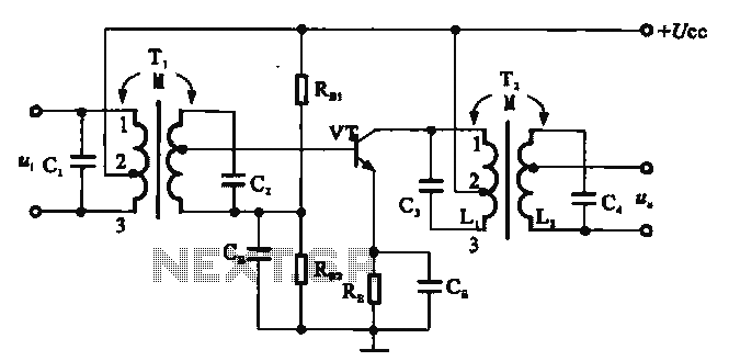
The double-tuned amplifier circuit is a specialized electronic configuration that enhances signal amplification by utilizing two resonant circuits. Each resonant circuit is designed to resonate at a specific frequency, allowing for improved selectivity and gain at that frequency. The transformers T1 and T2 serve as the core components of this configuration, with their primary and secondary coils strategically arranged to achieve the desired coupling effect.
The mutual coupling configuration, as depicted in Figure (a), relies on the magnetic interaction between the inductors. By adjusting the physical separation between inductors L1 and L2, the mutual inductance can be varied, thereby influencing the overall coupling coefficient. This adjustment enables fine-tuning of the amplifier's frequency response, allowing it to selectively amplify signals at the resonant frequency while attenuating others. The use of capacitors, such as C3, in conjunction with the inductors further refines the tuning process, ensuring that the amplifier operates efficiently within its intended frequency range.
On the other hand, the capacitive coupling configuration illustrated in Figure (b) employs an external capacitor, Ck, to control the coupling between the two tuners. This method allows for a more flexible tuning process, as the degree of capacitive coupling can be altered without physically moving the inductors. By adjusting the capacitance, the amplifier can be optimized for different signal frequencies, making it versatile for various applications.
Overall, the double-tuned amplifier circuit is an essential component in radio frequency (RF) applications, where precision and selectivity are crucial. Its design facilitates enhanced performance in communication systems, audio processing, and other electronic devices that require reliable signal amplification.There are two resonant circuits tuned amplifying circuit known as a double tuned amplifier circuit, i.e. the transformer Ti, T2 of the primary and secondary coils are provided has parallel resonance capacitor
has a resonance function. Depending on the coupling can be divided into two mutual coupling and capacitive coupling type Peng, Figure 3-20 below. Figure (a) shows the mutual inductance coupling double tuned amplifier which is tuned amplifier with the single exception that use Ll, C3 tuned circuit tuned circuit in place of a single secondary winding.
Using mutual coupling between the tough, secondary, or core that is changing the distance between the position of Li and Li can change their degree of coupling. Figure (b) shows the level of capacitive coupling amplifier tuned by changing an external capacitor Ck two tuners back road between the degree of coupling.
Related Circuits
A DC to DC converter circuit is designed to convert a DC voltage to another DC voltage with different levels. This specific converter transforms a +12 V DC input into a symmetrical output of +/-20 V DC. Such circuits...
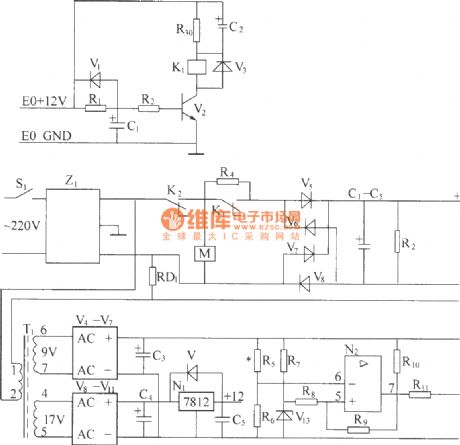
220V (50Hz) alternating voltage passes through the Z1 circuit filter, which filters the signal before sending it to the connection point of the AC overvoltage and undervoltage protection relay K2. During normal operation, the K2 connection point should be...
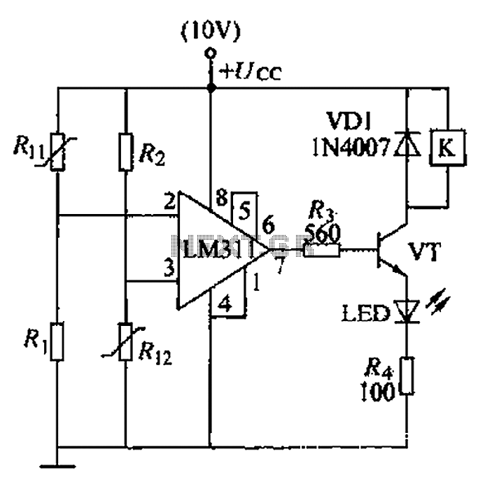
A boiler control circuit is designed to regulate the temperature of water in a hot water heating system. This circuit typically utilizes a comparator's comparison function to manage the heating equipment. The circuit includes a thermistor that forms a...
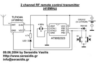
The following circuit illustrates a 3V power supply designed for an RF remote control circuit. This circuit is based on the AT90S2323 integrated circuit (IC). Features include a data rate of 2400 bps. The 3V power supply circuit for the...
The two circuits below illustrate opening a relay contact a short time after the ignition or light switch is turned off. The capacitor is charged and the relay is closed when the voltage at the diode anode rises to...
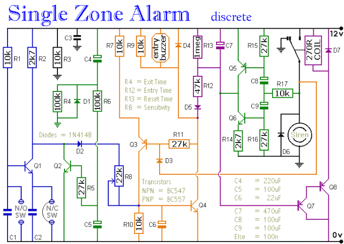
The circuit includes automatic entry and exit delays, a timed bell cut-off, and a system reset feature. It accommodates both normally open and normally closed switches, making it compatible with common input devices such as pressure mats, magnetic reed...
Warning: include(partials/cookie-banner.php): Failed to open stream: Permission denied in /var/www/html/nextgr/view-circuit.php on line 713
Warning: include(): Failed opening 'partials/cookie-banner.php' for inclusion (include_path='.:/usr/share/php') in /var/www/html/nextgr/view-circuit.php on line 713