Fire Alarms Circuit-Diagram-Smoke-Home-Security-Alarms

Various fire alarm circuits are discussed, featuring a new design that utilizes a thermistor and a timer. This circuit is straightforward and can be easily implemented. The thermistor exhibits low resistance at high temperatures and high resistance at low temperatures, making it suitable for fire detection. The IC1 (NE555) is configured as a free-running oscillator operating at audio frequency. Transistors T1 and T2 drive IC1, and the output from pin 3 of IC1 is connected to the base of transistor T3 (SL100), which activates the speaker. Additionally, there is a simple fire alarm circuit that employs a Light Dependent Resistor (LDR) and a lamp for smoke detection. This alarm is triggered by smoke generated during a fire, producing an audible alarm. In the absence of smoke, light from the bulb illuminates the LDR, resulting in low resistance and a voltage below 0.6V, keeping the transistor off. When smoke obscures the light from the bulb, the resistance of the LDR increases. Furthermore, the circuit leverages the fact that an increase in temperature during a fire causes a rise in the leakage current of transistor BC177 (Q1), which acts as the fire sensor. As the leakage current increases, transistor Q2 becomes biased and turns on, with the emitter of Q2 (BC108) connected to the base of Q3.
The fire alarm circuit utilizing a thermistor and timer is designed to detect temperature changes indicative of fire. The thermistor's characteristic of low resistance at elevated temperatures allows for effective sensing. The NE555 timer IC is configured in astable mode, generating a continuous square wave output at a specified frequency. This output is used to drive a small speaker, providing an audible alarm signal when a fire is detected.
Transistors T1 and T2 serve as amplifiers, ensuring that the NE555 timer is powered appropriately and can function efficiently. The output from the timer is fed into the base of transistor T3, which acts as a switch to control the speaker. When the circuit detects high temperatures, the thermistor's resistance drops, allowing current to flow and activating the alarm.
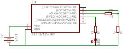
In parallel, the fire alarm circuit using an LDR is based on optical detection of smoke. The LDR senses changes in light intensity; under normal conditions, it has low resistance due to the light from the bulb. When smoke enters the detection area, it scatters and absorbs light, increasing the resistance of the LDR. This change in resistance causes the voltage across the LDR to rise, turning on the transistor that drives the alarm.
The inclusion of transistor BC177 as a temperature sensor enhances the circuit's capability to respond to fire conditions. The increase in leakage current as temperature rises biases transistor Q2, allowing it to conduct and trigger further alarm mechanisms. The output of Q2 can be used to drive additional circuits, such as visual indicators or communication systems, enhancing the overall functionality of the fire alarm system.
This fire alarm design is both compact and cost-effective, making it suitable for various applications, including residential and commercial environments. The combined use of thermistors, LDRs, and transistors creates a reliable sensing mechanism that can detect both temperature increases and smoke presence, ensuring timely alerts in the event of a fire outbreak.Many fire alarm circuits are presented here, but this time a new circuit using a thermistor and a timer to do the trick. The circuit is as simple and straight forward so that, it can be easily implemented. The thermistor offers a low resistance at high temperature and high resistance at low temperature. This phenomenon is employed here for sensing the fire. The IC1 (NE555) is configured as a free running oscillator at audio frequency. The transistors T1 and T2 drive IC1. The output (pin 3) of IC1 is couples to base of transistor T3 (SL100), which drives the speaker Here is a simple fire alarm circuit based on a Light Dependent Resistor (LDR) and lamp pair for sensing the fire. The alarm works by sensing the smoke produced during fire. The circuit produces an audible alarm when the fire breaks out with smoke. When there is no smoke the light from the bulb will be directly falling on the LDR. The LDR resistance will be low and so the voltage across it (below 0. 6V). The transistor will be OFF and nothing happens. When there is sufficient smoke to mask the light from falling on LDR, the LDR resistance When there is a fire breakout in the room the temperature increases.
This ultra compact and low cost fire alarm senses fire breakout based on this fact. Transistor BC177 (Q1) is used as the fire sensor here. When the temperature increases the leakage current of this transistor also increases. The circuit is designed so that when there is an increase in the leakage current of Q1, transistor Q2 will get biased. As a result when there is a fire breakout the transistor Q2 will be on. The emitter of Q2 (BC 108) is connected to the base of Q3(AC 🔗 External reference


