
30m Band Receiver
Parts list
Parts No. Value
P1 1 kOhm potentiometer
R1, R2 10 kOhm
C1, 3 5 .. 90 pF trimmer capacitor
C2 3,9 pF
C4 2 x 20 pF
VHFbroadcast variable capacitor
C5 100 pF
C6 220 pF
C7 150 pF
C8 0,1 u F
C9, 10 47 nF
C11 2,2 u F
C12 100 u F, 25 V
L1, 2 T50-2, 30 turns prim. / 3 turns sec.
L3 T50-2, 30 turns
Dr1 33 mH
IC2 NE612 DIP
IC2 78L06
IC3 TL072 DIP e.g.
KH Headphone Ri > 60 Ohm
The direct conversion receiver is a compact and efficient design that operates within a frequency range of 10050 kHz to 10250 kHz. The core components include a bandpass filter, a mixer integrated circuit (IC), a variable frequency oscillator (VFO), and an audio filter stage. The design is minimalistic, featuring only 22 components, making it suitable for hobbyists and beginners in electronics.
The oscillator section utilizes the NE612 IC, which can be configured as either a series-tuned Colpitts or Clapp oscillator. This flexibility allows for tuning adjustments to be made based on the specific components used in the circuit. The tuning of the circuit is achieved through careful adjustment of the number of turns on inductor L3 and the capacitance of capacitor C7, which are critical for achieving the desired frequency response.
Following the mixer stage, the output is processed by a selective audio amplifier that enhances the audio frequency (AF) signals while suppressing unwanted radio frequency (RF) components. Capacitors C9 and C10 play a vital role in filtering out these RF products, ensuring that only the desired AF signals are passed to the TL072 dual op-amp, which is configured in a non-inverting configuration. The audio frequency stage is designed to provide a significant gain of 46 dB at a resonant frequency of 660 Hz, making it suitable for audio applications.
Volume control is implemented through a potentiometer (P1) connected at the antenna terminal, allowing for user-adjustable audio output levels. It is important to note that the TL072 outputs are not low impedance, necessitating the use of a 470-ohm resistor in series when connecting headphones with an impedance greater than 60 ohms.
The receiver operates within a voltage range of 8V to 15V, with the audio filter stage powered directly from this supply voltage. Meanwhile, the mixer circuit receives a stable +6V regulated supply from a 78L06 voltage regulator, ensuring consistent performance. The overall current consumption of the receiver is approximately 6 mA under no input signal conditions, with potential savings of 1 to 2 mA achievable by using a low quiescent current regulator.
For alignment purposes, it is recommended to use an existing receiver to check the VFO frequency. Tuning adjustments can be made using the variable capacitor to achieve the desired reception frequency across the specified range. This straightforward approach to design and construction makes this direct conversion receiver an excellent project for those interested in radio frequency applications.The direct conversion receiver described consists of only a bandpass filter, mixer IC, VFO and audio filter. With only 22 parts, this simple circuit should take a few hours at the weekend to construct. For extra simplicity, eliminate L1 & C1 and connect C2 to the slider of P1. The oscillator section of the NE612 is configured as either a series-tuned Colpitts- or Clapp oscillator.
Depending on the parts the receive range is from 10050 kHz to 10250 kHz. Due to component tolerances the number of turns and/or the capacity of L3 and C7 are adjusted to tune the required portion of the band. The mixer stage is followed by a selective audio amplifier. Balanced DC voltage levels at the mixer outputs and amplifier inputs allow a component saving direct coupling. After suppressing the unwanted RF products by C9 and C10 the remaining AF is passed through to the non-inverting inputs of TL072 dual op amp.
A series resonant circuit, built out of Dr1 and C1, aids some AF selectivity. The AF stage has a gain of 46 dB at its 660 Hz resonant frequency. Audio volume is controlled by the attenuator P1 at the antenna terminal. The TL072 outputs aren't of low impedance. So, when connecting 60 ohm headphones one should arrange a 470 ohm resistor in series. The receiver operates in a voltage range from Ub=8 ... 15 V. The AF stage is supplied directly by Ub and the mixer gets a +6 V constant voltage from IC2. The receivers current consumption is approx. 6 mA with no input signal. You can save 1 ... 2 mA when using a 6 V regulator type with lower quiescent current. Alignment For the receiver alignment use of an existing receiver is recommended. Check the VFO frequency first. Receiver tuning should be possible between 10050 kHz (C4 max.) and 10250 kHz (C4 min.) by means of the variable capacitor. For this, listen to the VFO signal on the other receiver. Parts list Parts No. Value P1 1 kOhm potentiometer R1, R2 10 kOhm C1, 3 5 .. 90 pF trimmer capacitor C2 3,9 pF C4 2 x 20 pF VHFbroadcast variable capacitor C5 100 pF C6 220 pF C7 150 pF C8 0,1 u F C9, 10 47 nF C11 2,2 u F C12 100 u F, 25 V L1, 2 T50-2, 30 turns prim.
/ 3 turns sec. L3 T50-2, 30 turns Dr1 33 mH IC2 NE612 DIP IC2 78L06 IC3 TL072 DIP e.g. KH Headphone Ri > 60 Ohm 🔗 External reference
Related Circuits
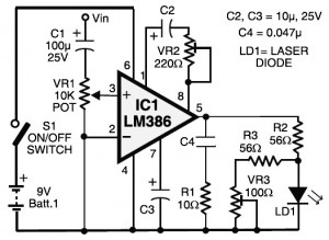
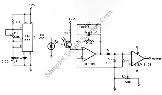
Laser communication system circuit diagram. The circuit module consists of a transmitter and a receiver that utilize the IC LM386. It is powered by a 9V battery. The laser communication system is designed to facilitate wireless data transmission using modulated...
The circuit is designed to operate at 25 kHz. The data stream controls the 2N4401 transistor, turning it fully on or off based on the coded state. This action switches the series of infrared LEDs on and off. The...
The figure illustrates a bilateral band modem circuit utilizing the NE561B component. The input modulating signal operates at a loading frequency of f0 = 1 MHz. When the AM modulation signal is applied to the input terminal of the...
Most telephone equipment today utilizes a DTMF receiver integrated circuit (IC). A widely used DTMF receiver IC is the Motorola MT8870, which consists of 18 pins and is employed in telephones and various other applications. When projects utilizing this...
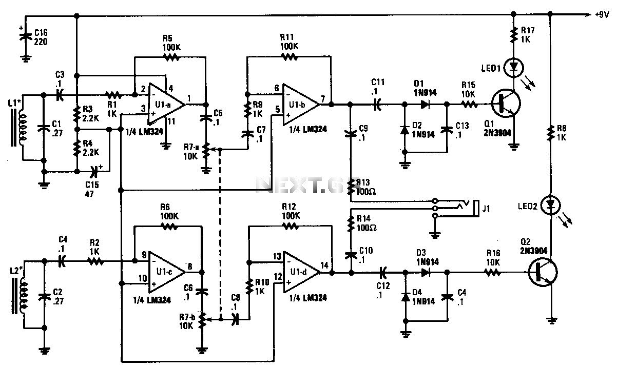
The tracer receiver is a stereo audio amplifier and detector circuit that operates at a frequency close to 1 kHz. Inductors L1 and L2 are hand-wound coils, each consisting of 200 turns of #26 wire on 2-inch ferrite cores,...
The infrared transmitter and receiver circuit depicted in the schematic diagram can function as a remote control. The transmitter operates as an oscillator circuit, with the frequency adjustable via the R1 potentiometer (or trimmer pot). This oscillation ensures that...