
DTMF Receiver IC MT8870 Tester
The described DTMF receiver testing circuit is designed to facilitate the verification of the Motorola MT8870 IC's functionality in various applications. The circuit's configuration allows for effective tone detection and conversion, ensuring that the output accurately represents the input from the telephone keypad. The inclusion of protection mechanisms, such as transient voltage suppression through zener diodes, enhances the circuit's reliability in real-world applications where electrical noise and surges may be present.
The balanced differential amplifier input is instrumental in minimizing interference from common-mode signals, which is critical in maintaining signal integrity, especially in telecommunication environments. The use of a multipurpose PCB or breadboard for assembly allows for flexibility in testing and prototyping, catering to both educational and professional settings.
The LED indicators provide immediate visual feedback regarding the binary output corresponding to the pressed keys, facilitating quick diagnostics. The optional guard time adjustment circuit allows for customization based on specific application needs, ensuring adaptability in various scenarios. Overall, this circuit serves as a practical tool for engineers and technicians to efficiently assess the performance of DTMF receiver ICs in telecommunication devices.Today, most telephone equipment use a DTMF receiver IC. One common DTMF receiver IC is the Motorola MT8870 that is widely used in electronic communications circuits. The MT8870 isan 18-pin IC. It is used in telephones and a variety of other applications. When a proper output is not obtained in projects using this IC, engineers or technicians need to test this IC separately. A quick testing of this IC could save a lot of time in research labs and manufacturing industries of communication instruments. Here`s a small and handy tester circuit for the DTMF IC. It can be assembled on a multipurpose PCB with an 18-pin IC base. One can also test the IC on a simple breadboard. For optimum working of telephone equipment, the DTMF receiver must be designed to recognise a valid tone pair greater than 40 ms in duration and to accept successive digit tone-pairs that are greater than 40 ms apart.
However, for other applications like remote controls and radio communications, the tone duration may differ due to noise considerations. Therefore, by adding an extra resistor and steering diode the tone duration can be set to different values.
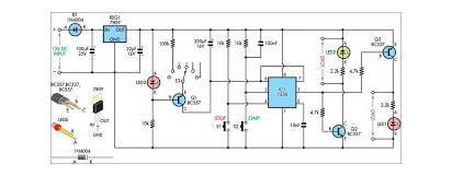
The circuit is configured in balanced-line mode. To reject common-mode noise signals, a balanced differential amplifier input is used. The circuit also provides an excellent bridging interface across a properly terminated telephone line. Transient protection may be achieved by splitting the input resistors and inserting zener diodes (ZD1 and ZD2) to achieve voltage clamping.
This allows the transient energy to be dissipated in the resistors and diodes, and limits the maximum voltage that may appear at the inputs. Whenever you press any key on your local telephone keypad, the delayed steering (Std) output of the IC goes high on receiving the tone-pair, causing LED5 (connected to pin 15 of IC via resistor R15) to glow.
It will be high for a duration depending on the values of capacitor and resistors at pins 16 and 17. The optional circuit shown within dotted line is used for guard time adjustment. The LEDs connected via resistors R11 to R14 at pins 11 through 14, respectively, indicate the output of the IC. The tone-pair DTMF (dual-tone multi-frequency) generated by pressing the telephone button is converted into binary values internally in the IC.
The binary values are indicated by glowing of LEDs at the output pins of the IC. LED1 represents the lowest significant bit (LSB) and LED4 represents the most significant bit (MSB). So, when you dial a number, say, 5, LED1 and LED3 will glow, which is equal to 0101. Similarly, for everyother number dialled on your telephone, the corresponding LEDs will glow. Thus, a non-defective IC should indicate proper binary values corresponding to the decimal number pressed on your telephone keypad. To test the DTMF IC 8870/KT3170, proceed as follows: 1. Connect local telephone and the circuit in parallel to the same telephone line. 2. Switch on S1. (Switch on auxiliary switch S2 only if keys A, B, C, and D are to be used. ) 4. Now push key *` to generate DTMF tone. 5. Push any decimal key from the telephone keypad. 6. Observe the equivalent binary as shown in the table. 7. If the binary number implied by glowing of LED1 to LED4 is equivalent to the pressed key number (decimal/A, B, C, or D), the DTMF IC 8870 is correct.
Keys A, B, C, and D on the telephone keypad are used for special signalling and are not available on standard pushbutton telephone keypads. Pin 5 of the IC is pulled down to ground through resistor R8. Switch on auxiliary switch S2. Now the high logic at pin 5 enables the detection of tones representing characters A, B, C, and D. 🔗 External reference
Related Circuits
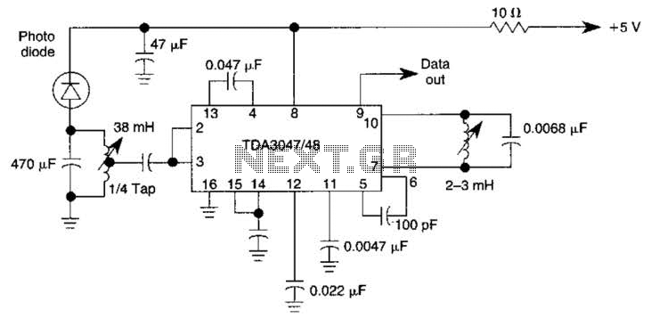
The circuit operates from a 5-V supply and has a current consumption of 2 mA. The output functions as a current source that can drive or suppress a current exceeding 75 mA with a voltage swing of 4.5 V....
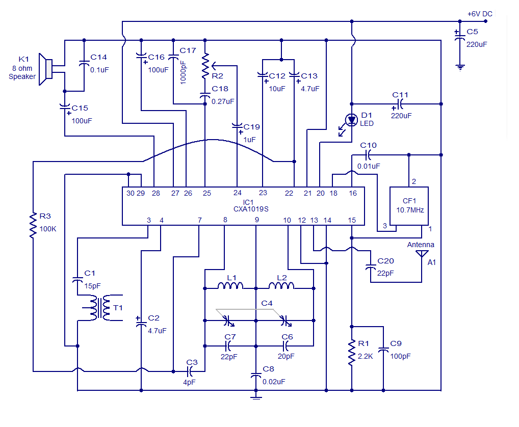
It is a high-quality FM receiver circuit based on the IC CXA1019. The CXA1019 is a monolithic silicon bipolar radio FM/AM receiver IC designed for Sony. The built-in circuitry within the CXA1019 includes an RF amplifier, mixer, oscillator, amplifier,...
IR detector diode D1 intercepts the IR signal at around 40 kHz and feeds it from U1, a high-gain preamp, to PLL, U2, a 4046 configured to serve as an FM detector. U3 is an audio amplifier that feeds...
The Demodulating Receiver (A3017) features a 902 to 930 MHz 30-dB amplifier, a downshifter, a 60-dB 50-MHz limiting IF amplifier, a frequency discriminator, and an amplitude demodulator. The A301701A circuit board also includes additional copies of the A3016SO SAW...
This design will interest technicians who work on pneumatically operated valves and other 4-20mA current loop controlled devices. Although the 4-20mA signal is commonly used in industrial applications for transmitting sensor data and controlling devices, it is essential to...
Acoustic check of transistor and diode junctions. Also suitable as a continuity tester. Short circuits or broken PCB tracks can be easily recognized. The acoustic check of transistor and diode junctions is a method used to assess the functionality of...