
30V from 5V converter
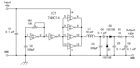
This circuit design involves a power supply capable of converting a +5V input into a +30V output, utilizing a combination of oscillation and rectification techniques. The primary component responsible for the oscillation is a Schmitt trigger inverter, which is known for its hysteresis characteristics. This feature allows the inverter to provide a stable square wave output, which is crucial for the subsequent conversion of direct current (DC) to alternating current (AC).
The oscillator circuit, formed by the Schmitt trigger, drives a resonant circuit that enhances the efficiency of the AC generation process. The resonance circuit typically consists of an inductor and a capacitor, which work together to create oscillations at a desired frequency. This oscillation is then transformed into a higher voltage AC signal.
Following the AC generation, a voltage amplification rectification circuit is employed to convert the alternating voltage back into a higher direct current voltage, specifically targeting +50V. This is achieved through a combination of transformers and rectifiers that effectively step up the voltage and ensure that the output is a smooth DC signal.
It is important to note that the output voltage of this power supply is sensitive to changes in load conditions. This characteristic makes it suitable for applications where the load remains constant or where variations in output voltage are permissible. Thus, the power supply can be effectively utilized in circuits that do not require strict voltage regulation, allowing for flexibility in various electronic applications.I made the power supply which makes about +30V with +5V power supply. The direct current is changed into the alternating current by the oscillator which used the schmitt trigger inverter which has the hysteresis characteristic and the resonance circuit. The high DC voltage (+50V) is made with the alternating voltage using the voltage amplification rectification circuit.
The output voltage of this circuit changes mainly when the load changes. So, this power supply can be used only as the power supply of the circuit that the load is constant or the circuit which doesn't have a problem even if the voltage changes. 🔗 External reference
Related Circuits
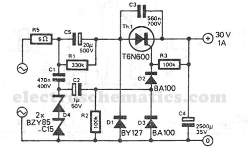
This transformerless power supply circuit is designed for medium current applications. During the negative half period, the capacitor C5 is charged to the peak voltage of the network. The positive half wave will trigger the thyristor, allowing the electric...
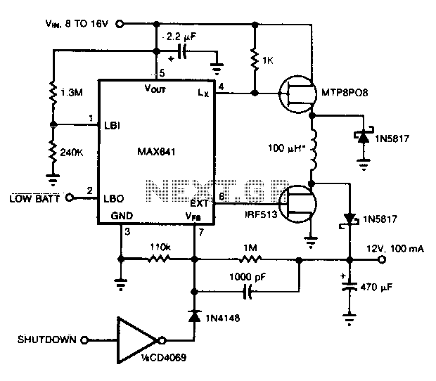
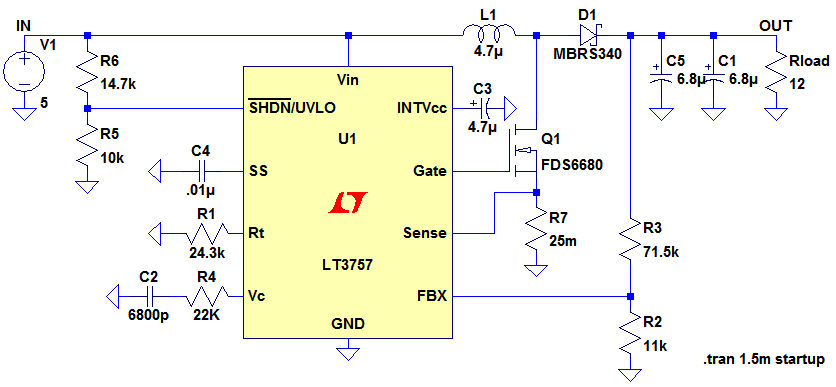
This converter can accommodate wide input voltage swings, such as the 8 to 15 V range typical of a 12 V sealed lead-acid battery. The low battery output indicates when the input voltage drops below 8 V. Pulling the...
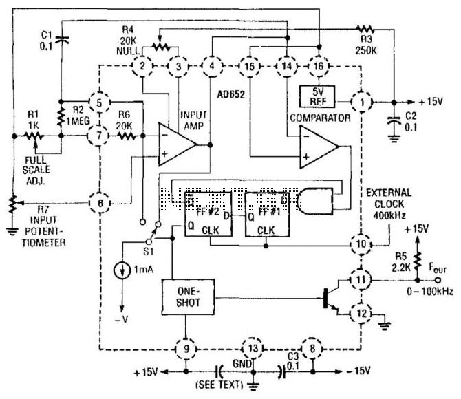
In this application, an AD652 integrated circuit (IC) is utilized in a synchronized voltage-to-frequency (V/F) converter that takes its input from the position of a potentiometer. This setup can represent the position of a mechanical component, weight, size, etc.,...
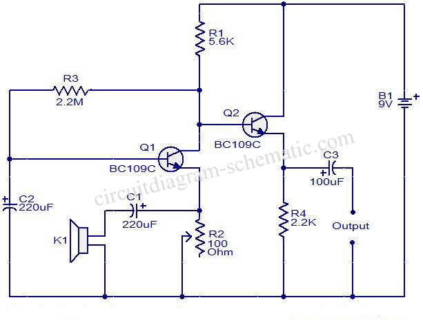
This circuit diagram illustrates the conversion of a speaker into a microphone. When sound waves impact the diaphragm of a speaker, fluctuations occur in the coil, generating an induced voltage. This induced voltage is typically substantial but low in...
Ignore components C1, C2, R3. The MOSFET, Q1, switches on, creating a short circuit between the right-hand side of the inductor, L1, and ground (0V). A fixed voltage of 3.3V is applied across the inductor, causing its current to...
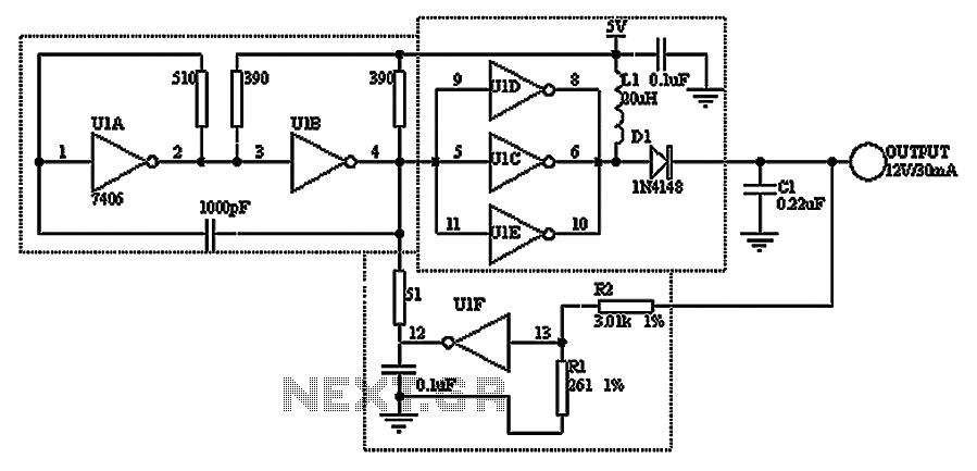
A TTL hex inverter circuit can function as a DC/DC converter, converting 5V to 12V. This circuit encompasses all necessary functionalities for DC/DC conversion. It relies on a TTL switching threshold voltage regulator. The components U1A and U1B form...