
speaker to microphone circuit converter
The circuit operates on the principle of electromagnetic induction, where the movement of the speaker diaphragm in response to sound waves creates variations in the magnetic field surrounding the coil. This results in an alternating current (AC) voltage that can be harnessed as an audio signal. The speaker, originally designed to convert electrical signals into sound, is repurposed to perform the opposite function—capturing sound and converting it back into electrical signals.
The key components of the circuit include the speaker, a transistor, and passive components such as resistors and capacitors. The speaker acts as the input transducer, while the transistor functions as the amplifier, boosting the weak audio signal generated by the speaker.
The circuit may utilize a common-emitter configuration for the transistor, which provides significant voltage gain. A resistor is connected to the collector of the transistor to set the operating point and ensure proper biasing. Additionally, a coupling capacitor may be employed to block any DC component from the output, allowing only the amplified AC audio signal to pass through.
To enhance performance, a power supply circuit is included to provide the necessary voltage for the transistor's operation. The overall design must consider the impedance matching between the speaker and the transistor to maximize signal transfer and minimize distortion.
This circuit can be used in various applications, such as audio recording, communication devices, and sound sensing systems, showcasing the versatility of converting a speaker into a functional microphone through careful circuit design.This circuit is a circuit diagram to convert the speaker into the microphone. In principle When sound waves fall on the diaphragm of a speaker, there will be fluctuations in the coil and the induced voltage will be no small proportion. This induced voltage is usually very large and useful low. Here, the low voltage circuit using a transistor amplified to produce a reasonable output 🔗 External reference
Related Circuits
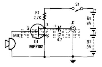
This preamplifier utilizes a small dynamic microphone connected to the gate of Q1. R1 acts as a load resistor. The audio output is taken from the negative side of C1 to ground. The output voltage will range between 10...
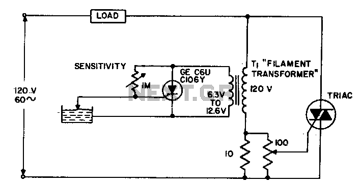
The circuit supplies power to the load until water conducts through the probe, allowing gate current to bypass from the low current SCR. This configuration provides an isolated low voltage probe to meet safety requirements. The described circuit operates as...
NOTE: There is no guarantee as to the suitability of said circuits and information for any purpose whatsoever other than as a self-training aid. I.E. If it blows your equipments, trashes your hard disc, wipes your backup, burns your...
The 8051 microcontroller features a transmit channel and a receive channel for serial communication. The transmit data pin (TXD) is designated as P3.1, while the receive data pin (RXD) is located at P3.0. The serial signals on these pins...
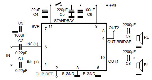
The car radio application utilizes a Class AB Audio Power Amplifier, typically featuring the TDA7360 IC. This amplifier provides 22W output in either bridge or stereo configuration and includes several beneficial features such as a minimal requirement for external...
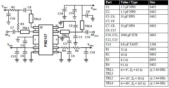
This RFIC amplifier operates in the 2400 MHz ISM band and features a two-stage design that is off-chip matched to ensure optimal performance across various applications. Powered by a 5-volt supply, the PM2107 can deliver 1 watt of saturated...
Warning: include(partials/cookie-banner.php): Failed to open stream: Permission denied in /var/www/html/nextgr/view-circuit.php on line 713
Warning: include(): Failed opening 'partials/cookie-banner.php' for inclusion (include_path='.:/usr/share/php') in /var/www/html/nextgr/view-circuit.php on line 713