
30w vhf fm broadcast amplifier
The 30-watt amplifier circuit is engineered for efficient amplification within the FM broadcast band, utilizing a 2SC1946A transistor that is optimized for high-frequency applications. The circuit's design emphasizes stability and output quality, achieved through the integration of a Butterworth low-pass filter, which effectively attenuates unwanted harmonics while allowing the desired frequency range to pass with minimal distortion.
The choice of 16-gauge wire for coil construction is significant; this gauge provides a balance between resistance and inductance, ensuring that the coils can handle the required current without excessive heating. The use of copper or silver wire can enhance the circuit's performance due to their superior electrical conductivity. The decoupled feedline is critical for maintaining signal integrity, preventing feedback that could lead to oscillations or noise.
The snubber circuit, along with capacitors C3, R2, and C6, plays a vital role in stabilizing the amplifier's operation by damping oscillations and ensuring that the amplifier remains within its intended operational parameters. The addition of a 180-ohm resistor in parallel with the amplifier at L7 is a precautionary measure to further suppress any unwanted VHF signals that may arise during operation.
In the configuration for a 60-watt amplifier, the use of two 2SC1946A transistors arranged at 90 degrees allows for effective power combining, which is essential for achieving higher output levels. The power combiner network must be carefully designed to ensure that the phase and amplitude of the signals from both transistors are aligned, thus maximizing the efficiency of the amplification process.
Overall, this amplifier circuit is a robust solution for applications requiring reliable performance within the VHF range, with thoughtful design choices that enhance both stability and output quality.The 30 watt amplifier circuit shown below provides an appropriate power boost with an input of 4 watt up to 6 watts. The circuit is designed to cover 88-108MHz FM Broadcast Band. However, the circuit is very stable at my place and provides a clean-output through seven (7) element Butter-worth low-pass filter.
The heart of the circuit is 2SC1946A V HF RF power transistor. The transistor is specifically designed to operate at frequencies up to 175 MHz, with very good results. The feedline is decoupled. The current amplifier can be more than 5 amps. All coils are made of 16gauge wire rod (copper or silver wire can do better) and HF RFC may be central torus (as shown in the image) or 6-hole ferrite R1 bead.
C3 and snubber circuit forms, while R2 and C6 prevent the amplifier self-oscillation in VHF, it is sometimes necessary to add 180 ohms in parallel with the amplifier will L7. That to dispel UNDESIRABLE VHF thereby reduce the spurious level. The 60Watts VHF power amplifier using the above circuit. 2SC1946A Two transistors are arranged at 90 degrees to each other and their results were combined using "Network Power Combiner".
It is very difficult to combine skills in the VHF and UHF 🔗 External reference
Related Circuits
This project involved designing an audio amplifier capable of delivering substantial output power with a minimal number of components while maintaining quality. The power amplifier section consists of three transistors and a few resistors and capacitors configured in a...
An RF force amplifier for FM is essential for amateurs looking to enhance small transmitters, whether they are homemade or commercially available. The presented circuit can deliver 50-60W of RF power with an input control of 15-20W within the...
A compact power amplifier that delivers high-quality sound. It incorporates a NE5534 operational amplifier, known for its excellent performance, capable of handling low loads, providing high speed, and exhibiting low distortion. Additionally, it features two V-MOSFET transistors at the...
Ultra-low EMI, mono and stereo, Class D audio power amplifiers deliver Class AB performance while maintaining Class D efficiency. Maxim's spread spectrum modulation (SSM) combined with third-generation EMI reduction techniques minimizes EMI radiation by decreasing the high-frequency components of...
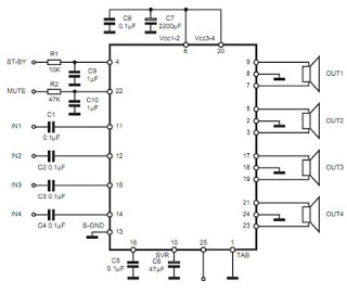
The TDA7383 features a fully complementary PNP/NPN output configuration, enabling a rail-to-rail output voltage swing without the need for bootstrap capacitors. This design significantly reduces the component count, allowing for compact assemblies. An integrated clipping detector facilitates gain compression...
This design is based on an 18 Watt Audio Amplifier and was developed primarily to address the needs of users who have difficulty locating the TLE2141C chip. It utilizes the commonly available NE5532 Dual IC; however, its power output...