
30 Watt Audio Power Amplifier Schematic
The audio amplifier circuit is designed with a focus on simplicity and efficiency, utilizing a minimal parts count to achieve high performance. The three-transistor amplifier stage operates in a class AB configuration, allowing for efficient power delivery and reduced heat generation. The choice of a shunt feedback configuration enhances linearity and stability, contributing to the low THD figures observed during testing.
The regulated power supply is a critical component, providing a stable voltage to the amplifier and preamp stages, ensuring consistent performance across varying load conditions. The LM317T voltage regulator, augmented with a PNP transistor, allows for the handling of higher current demands while maintaining regulation. The power supply design also includes filtering capacitors to further reduce ripple and noise, enhancing the overall audio quality.
The preamp section is equipped with a Baxandall tone control circuit, allowing users to adjust bass and treble frequencies to their preference. This stage is designed to maintain low noise levels while providing sufficient gain to drive the power amplifier effectively. The bootstrapped design of the tone control stage minimizes distortion and maintains a low output impedance, ensuring compatibility with the subsequent amplifier stage.
In summary, the audio amplifier project showcases an efficient design that balances performance and simplicity. By employing a regulated power supply and a minimalistic approach to component selection, the circuit achieves impressive audio fidelity suitable for a wide range of audio sources. The flexibility in the design allows for customization, making it adaptable to various applications while maintaining high-quality audio output.This project was a sort of challenge: designing an audio amplifier capable of delivering a decent output power with a minimum parts count, without sacrificing quality. The Power Amplifier section employs only three transistors and a handful of resistors and capacitors in a shunt feedback configuration but can deliver more than 18W into 8 Ohm with
0. 08% THD @ 1KHz at the onset of clipping (0. 04% @ 1W - 1KHz and 0. 02% @ 1W - 10KHz) and up to 30W into a 4 Ohm load. To obtain such a performance and to ensure overall stability of this very simple circuitry, a suitable regulated dc power supply is mandatory. This is not a snag because it also helps in keeping noise and hum of the preamp to very low levels and guarantees a predictable output power into different load impedance.
Finally, as the amplifier requires only a single rail supply, a very good dc voltage regulator capable of supplying more than 2 Amps @ 40V can be implemented with a few parts also. Switch off the supply, disconnect the Multimeter and reconnect it, set to measure at least 1Amp fsd, in series to the positive supply (the possible use of a second Multimeter in this place will be very welcomed).
Those lucky enough to reach an oscilloscope and a 1KHz sine wave generator, can drive the amplifier to the maximum output power and adjust R3 in order to obtain a symmetrical clipping of the sine wave displayed. The Preamp sensitivity and overload margin were designed to cope with most modern music program sources like CD players, Tape recorders, iPods, Computer audio outputs, Tuners etc.
The source selecting switches and input connectors are not shown and their number and arrangement are left to the constructor`s choice. To obtain a very high input overload margin, the volume control was placed at the preamp input. After a unity gain, impedance converter stage (Q1) a negative-feedback Baxandall-type Bass and Treble tone control stage was added.
As this stage must provide some gain (about 5. 6 times) a very low noise, "bootstrapped" two-transistors circuitry with FET-input was implemented. This stage features also excellent THD figures up to 4V RMS output and a low output impedance, necessary to drive properly the Mini-MosFet Power Amplifier, but can also be used for other purposes. A very good and powerful Regulated Power Supply section was implemented by simply adding a PNP power transistor to the excellent LM317T adjustable regulator chip.
In this way this circuit was able to deliver much more than the power required to drive two Mini-MosFet amplifiers to full output (at least 2Amp @ 40V into 4 Ohm load) without any appreciable effort. A power Transformer having a secondary winding rated at 35 - 36V and 50VA (i. e. about 1. 4Amp) is required if you intend to use Loudspeaker cabinets of 8 Ohm nominal impedance. To drive 4 Ohm loads at high power levels, a 70 - 75VA Transformer (2Amp at least) will be a better choice.
These transformers are usually center tapped: the central lead will be obviously left open. For the stereo version of this project, R16 and C11 in the Preamp will be in common to both channels: therefore, only one item each is necessary. In this case, R16 must be a 1K5 1/2W resistor. The value of C11 will remain unchanged. 🔗 External reference
Related Circuits
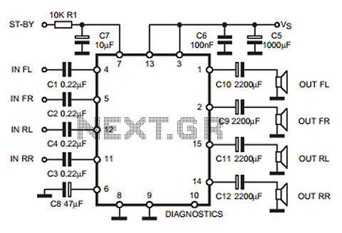
The following circuit illustrates a 35W quadruple amplifier and a 2 x 25W bridge amplifier based on the TDA7375 integrated circuit (IC). This circuit requires a minimal number of external components. Although initially designed for car applications, it can...
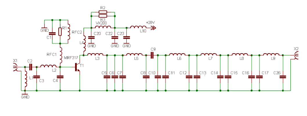
This power amplifier is equipped with a bipolar transistor, the famous MRF317. As in many FM amplifier applications, the power transistor is in a C class bias. All the impedance networks (input & output) have been determined by using...
This power supply circuit is highly stabilized that its output voltage will drop only 0.005% even though the load changes from 0 to 100%. Another excellent capability is that the output voltage will change only by 0.01% if the...
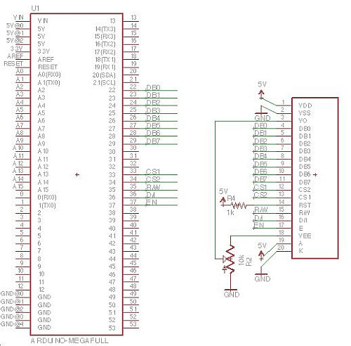
Displays are always beneficial. Until now, only 7-segment displays have been demonstrated for showing numbers using minimal resources. However, for displaying text or images, a simple LCD screen is required. There are basic LED screens available that operate on...
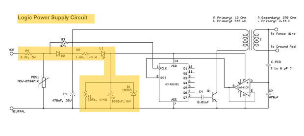
This electric fencing solution is essential for operation in regions with dry ground. It includes a schematic for an Electric Fence Charger, originally created by KC Mylrea in 1972. The purpose of this system is to power electric fences...
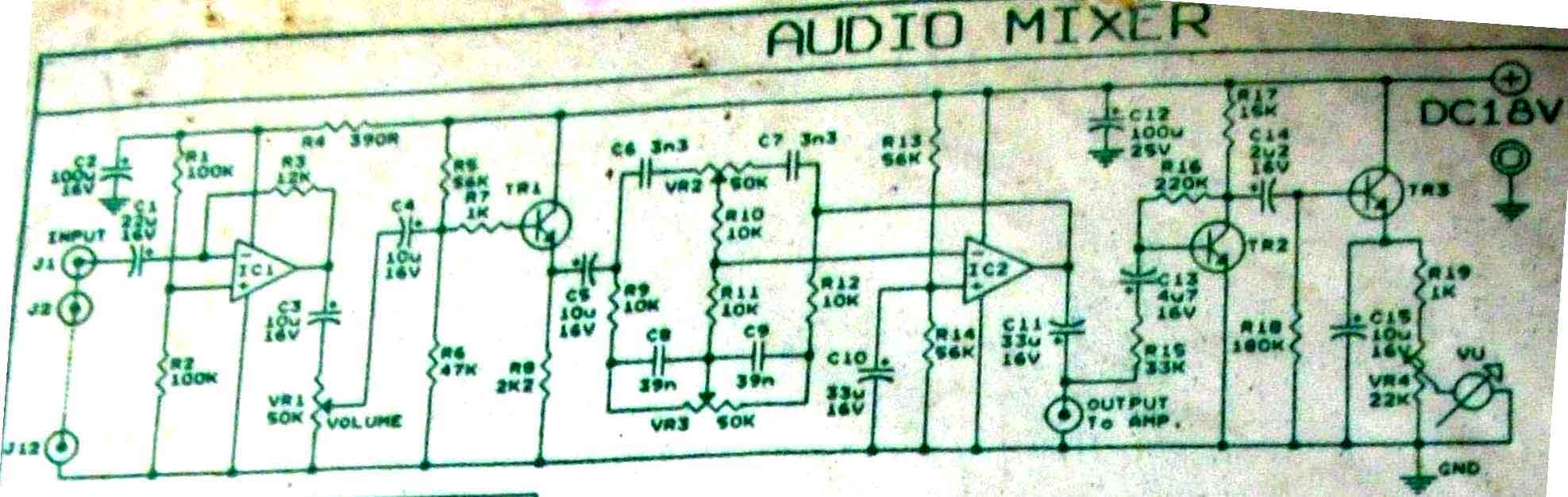
This is audio mixer circuit. The circuit is for one channel input, if you need, for example 5 channel mixer, then you need to build 5 similar circuits. The audio mixer circuit described is designed to handle a single channel...