
and filter 1 3 5w power rf amplifier
The RF amplifier circuit described is designed to boost the transmission power of FM signals, making it particularly useful for amateur radio enthusiasts. The BLY90 transistor, selected for its favorable gain characteristics, plays a critical role in the amplification process. With a gain of 5dB, it effectively amplifies the input signal from the transmitter, enhancing the output power significantly.
The circuit operates within the FM frequency range of 88-108 MHz, which is the standard band for FM broadcasting. The input stage of the amplifier accepts a signal from an existing transmitter, which typically outputs between 15-20W. This input signal is fed into the amplifier, where it is processed and amplified to a level of 50-60W.
For optimal performance, the output of the amplifier must be connected to either a dummy load or an antenna. A dummy load is often used during testing to prevent signal radiation and ensure that the amplifier operates correctly without broadcasting. If connecting to an antenna, a standing wave bridge should be utilized to match the impedance and minimize signal reflections, which can lead to inefficiencies and potential damage to the circuit.
Powering the amplifier requires a DC supply voltage in the range of 11-15V, with a current capacity of 4-5A. This specification is crucial for ensuring that the amplifier operates within its designed parameters without overheating or failing due to insufficient power.
The tuning of the amplifier is facilitated by four variable capacitors (C1-C4), which allow for fine adjustments to be made. By carefully tuning these capacitors, users can optimize the output power and ensure that the amplifier is functioning at peak efficiency. Once the adjustments are complete and the maximum output power is achieved, the amplifier is ready for deployment in an FM transmission application.
This RF amplifier circuit represents a valuable tool for amateur radio operators seeking to increase their transmission capabilities, providing a practical solution for enhancing signal strength and coverage.A amplifier of force RF for the FM, is always essential for the amateur that wants it strengthens some small transmitter, that likely already it has manufactured or has been supplied ready. The present circuit can give 50-60W RF force of expense, with control smaller than 15-20W in the region of frequencies of FM, that is to say in the 88-108MHZ.
Transistor that we selected for this manufacture is the BLY90, that has gain 5dB. If all they are it includes, you connect the exit of your transmitter (15-20W) in input the amplifier. The exit of amplifier him you will connect in some charge (dummy load) or in the aerial, through bridge stagnant waves.
Supply with tendency 11-15V your amplifier (power supply it should gives current 4-5A). Regulate the 4 variable C1-C4, until you take the biggest force of expense. The amplifier is ready. 🔗 External reference
Related Circuits
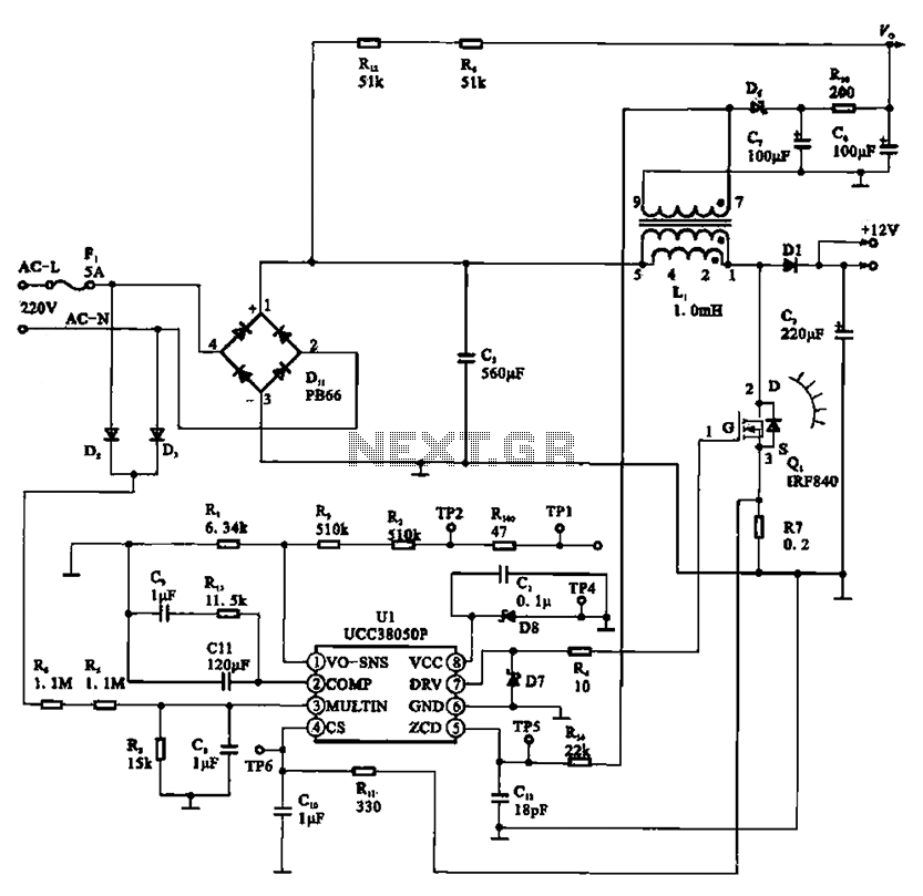
A typical laptop power adapter circuit converts an AC input of 22V through a rectifier and filter circuit to produce an output of +30V DC. This voltage is then processed by a switch oscillation circuit (U1, UCC38050P), which controls...
This is a convenient and straightforward general-purpose 50-watt amplifier. The amplifier features an input for connecting devices such as radios, TVs, or stereo equipment. Additionally, it includes a phono input suitable for connecting record players, guitars, microphones, or other...
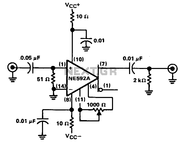
The circuit provides a voltage gain of 20 ±0.1 dB within a frequency range of 500 kHz to 50 MHz. The low-frequency response of the amplifier can be enhanced by increasing the value of the 0.05 µF capacitor connected...
The circuit was designed according to the RIAA implementation of a Hi-Fi phono preamplifier for the purpose of reproducing audio from a moving magnet cartridge. The RIAA (Recording Industry Association of America) equalization curve is essential for the accurate playback...
Most amplifiers operate at acoustic frequencies, sometimes requiring two or even three transformers instead of a single power transformer. This approach is more prevalent in high-end amplifiers, where enthusiasts often prioritize high fidelity over cost. In these setups, the...
The following circuit illustrates a Power Factor Correction (PFC) Switching Power Supply Circuit Diagram. Features include suitability for 1U (1.75-inch) form factor and minimization of input harmonics. The PFC Switching Power Supply Circuit is designed to enhance the efficiency of...
Warning: include(partials/cookie-banner.php): Failed to open stream: Permission denied in /var/www/html/nextgr/view-circuit.php on line 713
Warning: include(): Failed opening 'partials/cookie-banner.php' for inclusion (include_path='.:/usr/share/php') in /var/www/html/nextgr/view-circuit.php on line 713