
32.768 KHz Oscillator using Watch Crystal

The circuit described operates based on the oscillation of a 32.768 kHz crystal, a frequency commonly used in timekeeping applications due to its stability and accuracy. The crystal generates a precise square wave output, which is essential for timing applications. This output is then fed into a 15-stage binary counter, which divides the frequency down to a 1 Hz square wave, suitable for various timing applications.
The choice of the 4069 inverter is significant as it provides a clean and stable output waveform, which is critical for digital circuits that rely on precise timing signals. The inverter circuit enhances the signal integrity, reducing noise and distortion that could arise from alternative configurations, such as those using a single transistor.
The single transistor circuit, while capable of producing a square wave, tends to generate a ramping waveform. This characteristic may not be suitable for all applications, particularly where sharp transitions are required. However, its ability to swing the output across the full supply voltage range allows it to interface directly with CMOS binary counters, which typically require a full rail-to-rail signal for reliable operation.
Overall, the circuit design choices made in this application reflect a balance between waveform quality and operational requirements, ensuring that the generated square wave can effectively drive subsequent digital circuitry.Welcome to the weblog where we discuss about electronic circuits schematics, PCB design, diy kits and electronic projects diagrams. a 32. 768 KHz square wave from a common watch crystal. The output can be fed to a 15 stage binary counter to obtain a 1 second square wave. The circuit on the left using the 4069 inverter is recommended over the trans istor circuit and produces a better waveform. The single transistor circuit produces more of a ramping waveform but the output swings the full supply voltage range so it will easily drive the input to a CMOS binary counter. 🔗 External reference
Related Circuits
A crystal oscillator circuit is a straightforward oscillator circuit that can be easily understood through its schematic diagram. It serves as a replacement for a conventional oscillator network, which typically consists of an LC combination. This simplicity is also...
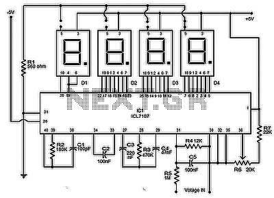
The circuit presented is a highly useful and accurate digital voltmeter featuring an LED display, utilizing the ICL7107 integrated circuit from Intersil. The ICL7107 is a high-performance, low-power, 3.5-digit analog-to-digital converter (ADC). This IC incorporates internal circuitry for seven-segment...

This voltage-controlled oscillator circuit is compact and exhibits good linearity. The precision can be better than 0.01% if properly constructed. The circuit provides three different output waveforms: square, triangle, and sawtooth, which are essential for music synthesizers and measurement...
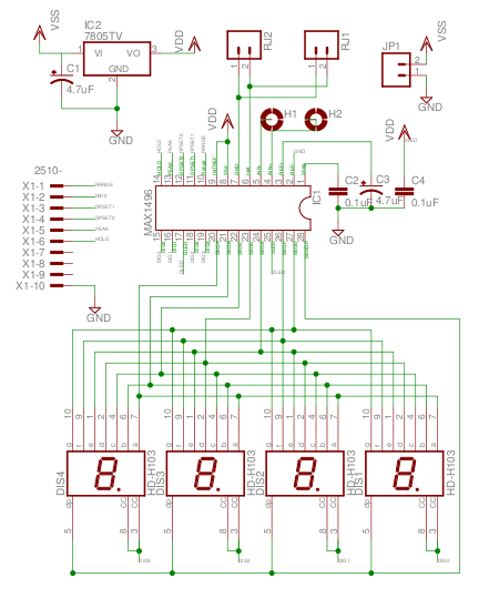
The MAX1496 is an analog-to-digital converter (ADC) that incorporates LED drivers, allowing for the construction of a 3 1/2 digit voltmeter using a minimal number of components. This device features both external and internal voltage reference options, along with...
This circuit generates a good 1KHz sinewave adopting the inverted Wien bridge configuration (C1-R3 & C2-R4). It features a variable output, low distortion and low output impedance in order to obtain good overload capability. A small filament bulb ensures...
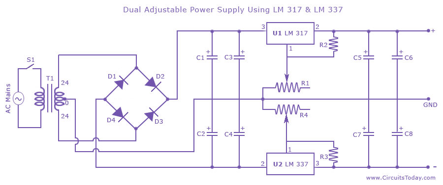
Dual adjustable power supply circuit with a diagram using IC LM317 and LM337. This variable power supply circuit has a range of 1.2 volts to 30 volts. The dual adjustable power supply circuit utilizes the LM317 and LM337 voltage regulators...